Sliding vane positive displacement pump having a fixed disc configuration to reduce slip paths

a positive displacement, sliding vane technology, applied in the direction of rotary/oscillating piston pump components, machines/engines, liquid fuel engines, etc., can solve the problems of known pump designs that have disadvantages, and achieve the effect of eliminating end clearance, eliminating slip formation, and improving sealing

Active Publication Date: 2016-10-25
DELAWARE CAPITAL FORMATION INC
View PDF15 Cites 0 Cited by
  • Summary
  • Abstract
  • Description
  • Claims
  • Application Information

AI Technical Summary

Benefits of technology

[0020]With this design, the discs rotate with the rotor and the end clearances are eliminated. This thereby eliminates the formation of slip between such end surfaces. More particularly in this design, the path of fluid traveling from the high pressure pump side near the outlet to the low pressure side of pump near the inlet is controlled with a radial clearance that is defined between the OD of each disc and the ID of the stationary head. This effectively eliminates the direct slip path extending radially across end faces of a rotor and the stationary discs that is present in the known design (FIGS. 1 and 2). This OD sealing method of the invention creates a better seal due to more torturous flow path (higher pressure loss) as well as a potential dynamic sealing due to boundary layer formation during operation.
[0021]The design of the invention provides a number of benefits. For example, this provides an improved method to reduce pumpage lost due to slip between discharge and inlet sides of a positive displacement vane pump which improves hydraulic efficiency. Since the axial end clearances are eliminated, the reliance upon the radial clearance at the OD of each disc allows for larger machining tolerances and / or internal pump clearances to improve machining cost and assembly. This also improves pump durability when it is necessary to use materials that are sensitive to galling such as nonmetallic or dissimilar metals used for the discs and head. There also is a lower amount of vane contact / wear on the vane width when the rotor / shaft and discs are axially located and set during assembly. With the known configuration of FIGS. 1 and 2, the ends of the vanes interface with the stationary discs and there could be high relative velocity between the vane ends and each stationary disc / head.
[0022]Additional advantages also exist. For example, the diameter of the rotor still may be much larger than a shaft. The discs are bolted or otherwise affixed to the rotor and rotate with the rotor shaft which eliminates the axial end faces. Since the disc OD is defined and located within the head, the dynamic clearance is now defined by and controlled on the OD of the disc and the ID of the head. These diameters can be easily machined in one operation which allows for precise location and size of the opposing head and disc diameters.
[0023]Further, clearances can be more precisely controlled, and perpendicularity tolerance of the rotor is less important since the end clearances are eliminated in the inventive design. Also, locating the clearances on the diameter creates a torturous flow path which improves flow lost due to slip. Still further, axial pump clearances can be increased which improves assembly and field repairability.
[0024]In addition to the preferred design described herein, other alternate configurations are disclosed. For example, the disc OD can be designed to further eliminate slip such as by providing a helical dynamic excluder (pump) or a labyrinth seal (multiple steps). Further, the discs and shaft may be integrated into a single piece, wherein the rotor would be clamped between two axial-extending shaft sections.
[0025]If desired, discs can be non-metallic or dissimilar metals while still avoiding galling or damage. If desired, metallic discs may be used depending on application, and providing a relatively small disc thickness in relation to metallic rotor reduces issues with thermal expansion of plastics used in metallic housings.

Problems solved by technology

Due to this end clearance, however, disadvantages are present with known pump designs.
Hence, these pump designs still exhibit disadvantages resulting from the slip which occurs between the stationary pump components and the rotor 45.

Method used


Image

  • Sliding vane positive displacement pump having a fixed disc configuration to reduce slip paths
  • Sliding vane positive displacement pump having a fixed disc configuration to reduce slip paths
  • Sliding vane positive displacement pump having a fixed disc configuration to reduce slip paths

Examples


Embodiment Construction

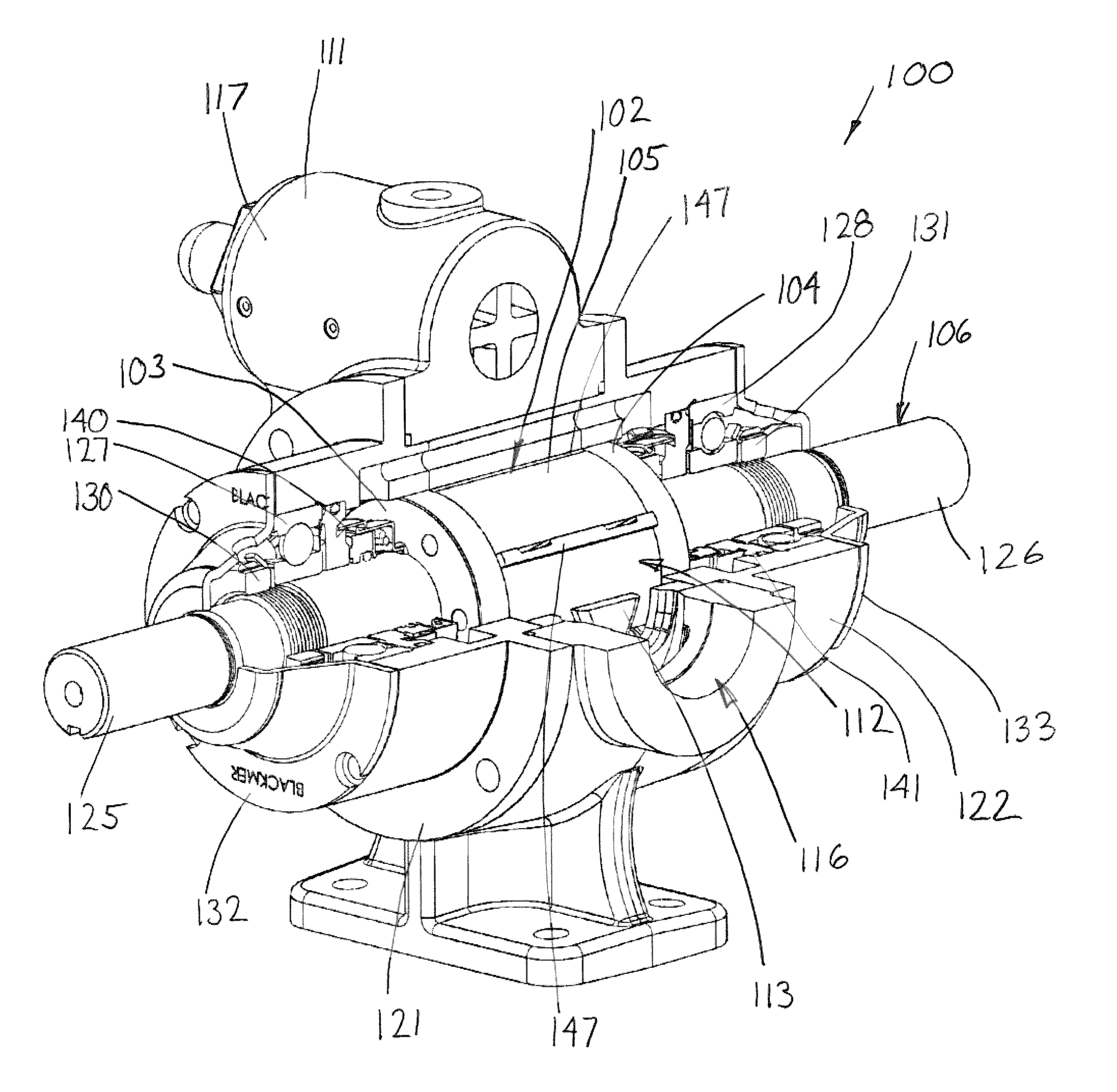
[0051]Referring to FIGS. 3 and 4, the invention relates to a sliding vane, positive displacement pump 100 which includes an inventive bolted or fixed disc rotor / shaft assembly 102 wherein two discs 103 and 104 are fixed to and rotate with the rotor 105 during rotation of a shaft 106.

[0052]Generally as to FIGS. 3-6, the sliding vane pump 100 includes a housing or casing 111 that defines a hollow section which is shaped to define a pump chamber 112. Typically, the pump chamber 112 is defined internally by a liner 113 that is stationarily supported in the casing 111 and has an eccentric, non-circular cross-sectional profile as seen in FIG. 8. As best seen in FIG. 8, the pump chamber 112 is supplied with process fluid through an inlet 115 and discharges from an outlet 116, which inlet 115 and outlet 116 respectively open radially into and out of the pump chamber 112 through the liner 113. The liner 113 has a generally cylindrical shape that includes radial fluid ports or passages 113A a...


PUM


Abstract

A sliding vane, positive displacement pump is provided which uses a fixed disc configuration wherein a rotor includes a pair of discs affixed to opposite faces of the rotor so as to rotate with the rotor / shaft. Preferably, the discs each have an outer diameter proximate the outer diameter of the rotor and define an outer disc surface which faces radially outwardly towards an opposing, inside surface of the pump head or other casing structure. A dynamic seal is provided along the outside disc diameter which eliminates the formation of slip between end surfaces. The path of fluid traveling from the high pressure pump side near the outlet to the low pressure side of pump near the inlet is controlled with a radial clearance that is defined between the OD of each disc and the ID of the stationary head. This effectively eliminates direct slip paths extending radially across axially-directed end faces.

Description

CROSS REFERENCE TO RELATED APPLICATIONS[0001]This application asserts priority from provisional application 61 / 647,276, filed on May 15, 2012, which is incorporated herein by reference.FIELD OF THE INVENTION[0002]The invention relates to a sliding vane positive displacement pump and more particularly, to a pump having an improved rotor construction which rotates within a pump casing to effect pumping.BACKGROUND OF THE INVENTION[0003]In sliding vane positive displacement pumps, such pumps are used in a number of different industrial and commercial processes to force fluid movement from a first location to a second location. One example of a sliding vane pump of this type is illustrated in FIGS. 1 and 2.[0004]The prior art sliding vane pump 10 includes a housing or casing 11 that defines a hollow section which is shaped to define a pump chamber 12. Typically, the pump chamber 12 is defined by a liner 13 that is stationarily supported in the casing 11 and has an eccentric, non-circular...

Claims


Application Information

Patent Timeline
Patent Type & Authority Patents(United States)
IPC IPC(8): F01C21/08F04C2/00F04C27/00F04C15/00F04C2/344
CPCF04C2/00F01C21/08F04C2/3442F04C15/0023F04C2240/20
Inventor WALTERS, MICHAEL D
Owner DELAWARE CAPITAL FORMATION INC
Why Eureka
Try Eureka