Glow Discharge Apparatus and Method with Lateral Rotating Arc Cathodes

a technology of lateral rotating arc cathodes and discharge apparatus, which is applied in the direction of electrolysis components, vacuum evaporation coatings, coatings, etc., can solve the problems of hard-arc burning on the substrate, difficult and sometimes even impossible optimization of conventional glow discharge, and practicable inability to clean the substrate surface uniformly using conventional glow discharge, etc., to achieve the effect of eliminating the formation of arc discharge and improving the stability of the arc-enhanced glow discharge process

Inactive Publication Date: 2014-10-23
PIVOT
View PDF3 Cites 1 Cited by
  • Summary
  • Abstract
  • Description
  • Claims
  • Application Information

AI Technical Summary

Benefits of technology

[0011]In order to generate electrons the system uses two rotary cylindrical electrodes equipped with rotary shields. One of the two cathodes is switched from negative pole of low voltage arc supply—the configuration used for the deposition of layers—to positive pole of current supply and creates therewith an ionization anode. This ionization anode in combination with the second cylindrical rotary cathode connected to a negative pole of low voltage arc supply in combination with use of the closed rotary shield, so that the second cathode is shielded from the samples, forms effective ionization supply. It is advantageous if the current supply connected to the ionization anode operates in pulse regime. It substantially improves stability of the arc-enhanced glow discharge process and eliminates formation of arc discharge on substrates.

Problems solved by technology

Therefore, it is practically impossible to clean the substrate surface uniformly using conventional glow discharge.
Optimization of the conventional glow discharge is difficult and sometimes even impossible.
However, the device of U.S. Pat. No. 5,294,322 A needs an additional ionization anode, which must be kept clean and needs maintenance between two processes.
There is also a risk of hard-arc burning on the substrates.

Method used


Image

  • Glow Discharge Apparatus and Method with Lateral Rotating Arc Cathodes
  • Glow Discharge Apparatus and Method with Lateral Rotating Arc Cathodes
  • Glow Discharge Apparatus and Method with Lateral Rotating Arc Cathodes

Examples


Embodiment Construction

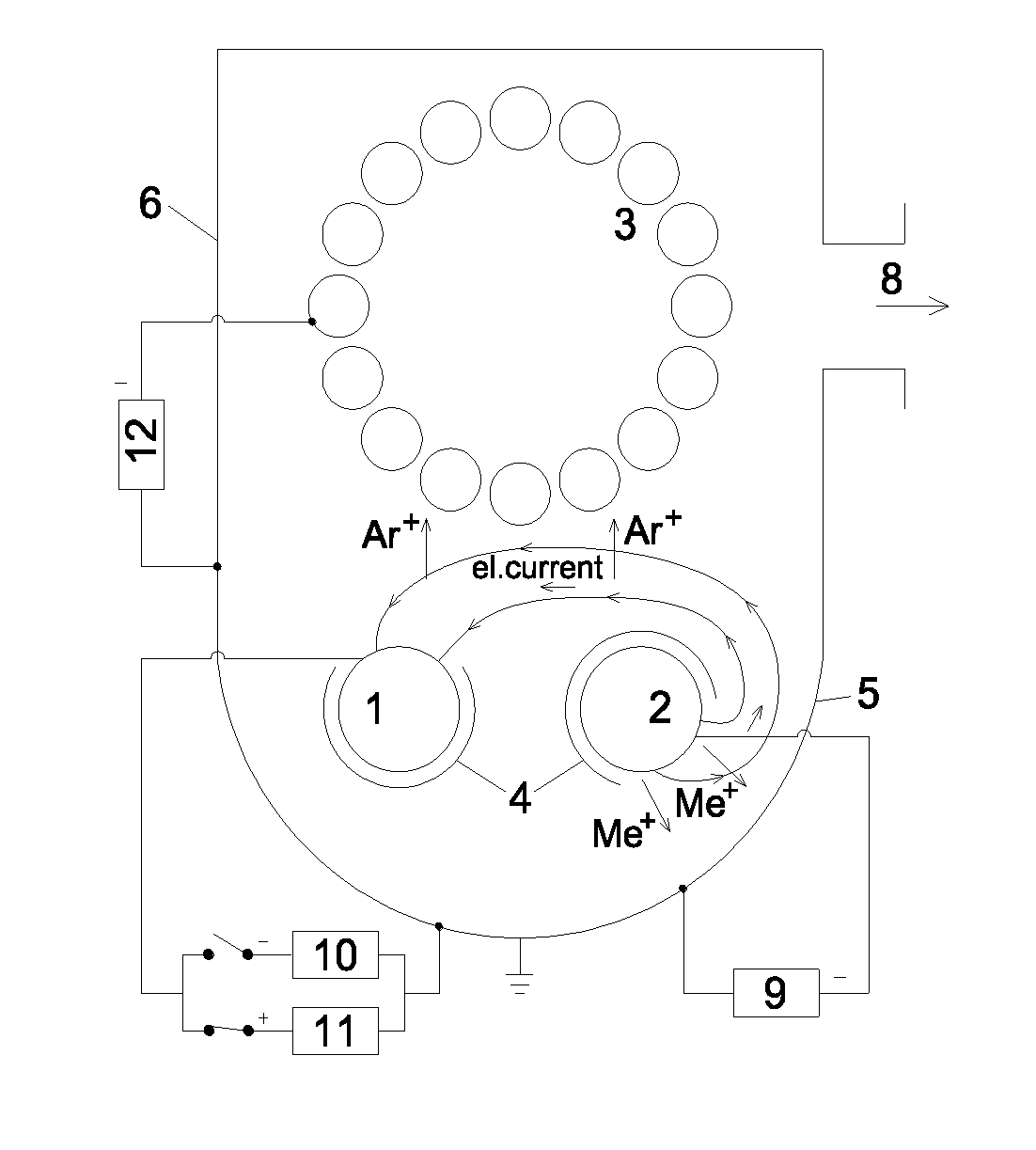
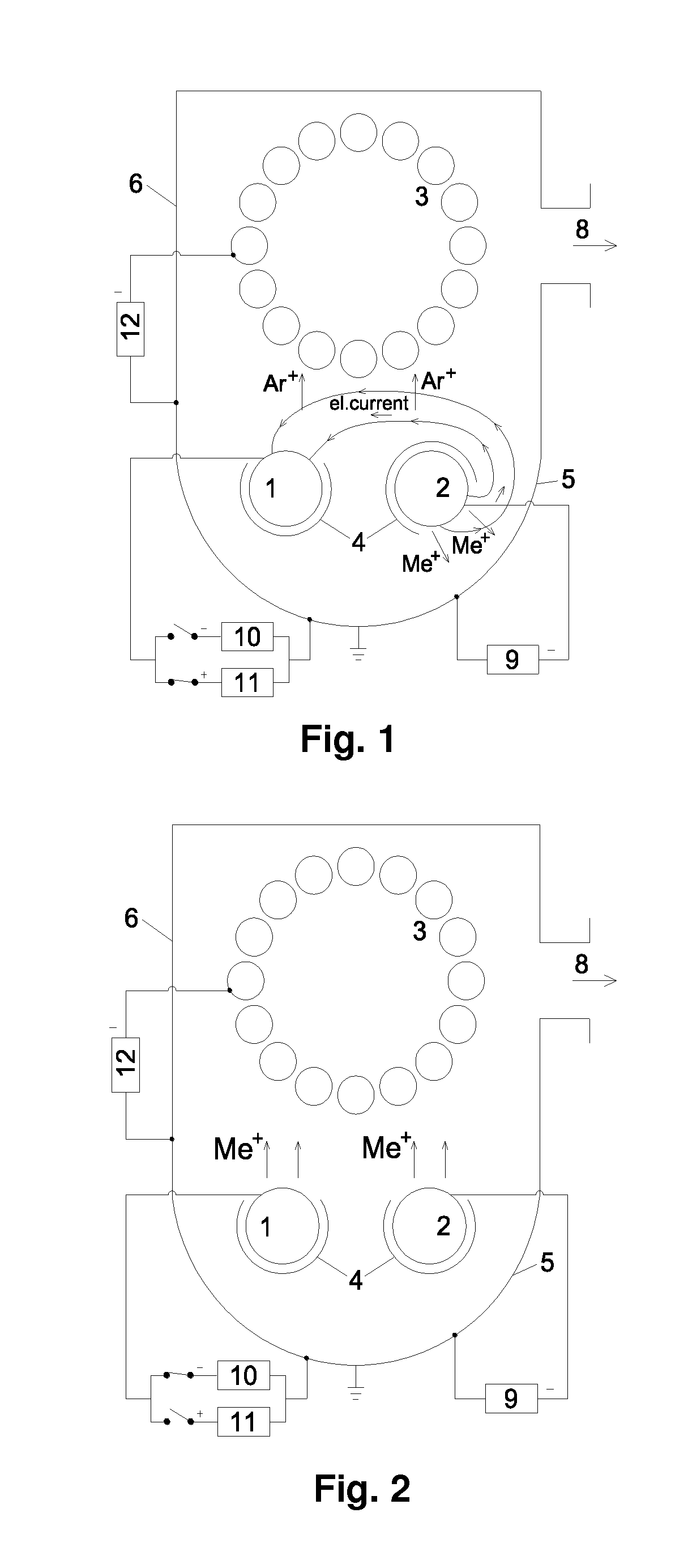
[0010]One object of the invention is to provide an apparatus for improving the above mentioned process using a Lateral Rotating Arc cathode (LARC) cathode acting as the anode, which can be cleaned immediately after the arc enhanced glow discharge, in-situ burning behind the shutter. This object of the invention is solved by the inventive method according to claim 1. Another object of the invention is to improve the corresponding process. This object of the invention is solved by the inventive method according to claim 10. The measures of the invention have primarily the effect that—for the production of Ar+ ions by arc-enchanced glow discharge processes as alternative method to a conventional Ar-glow discharge process—the ions are produced by inelastic collisions of electrons generated in arc and gas atoms.

[0011]In order to generate electrons the system uses two rotary cylindrical electrodes equipped with rotary shields. One of the two cathodes is switched from negative pole of low ...


PUM

PropertyMeasurementUnit
switching frequencyaaaaaaaaaa
arc currentaaaaaaaaaa
electrical potentialaaaaaaaaaa

Abstract

To improve the result of a glow discharge process is disclosed to be performed in a Physical Vapor Deposition (PVD) coating apparatus comprising a door, at least 2 lateral rotating cathodes with targets. The apparatus is equipped by rotating shields or tube shutters (4). The method comprises the steps of operating the apparatus so that the arc of said second electrode (2) burns directly to said door. The rotary shield or tube shutter on a first electrode (1) is open and said rotary shield or tube shutter (4) on a second electrode (2) is closed. Then a positive potential is applied on said first electrode (1), so that a potential between said second electrode (2) and said first electrode (1) is applied. The positive potential applied on said first electrode (1) is selected so that the electron stream does not burn only against the door since the electrons being affected by the higher potential to said first electrode (1).

Description

FIELD OF INVENTION[0001]The invention is related to a particular glow discharge apparatus and a corresponding method, which can be used in a special Physical Vapor Deposition (PVD) coating apparatus with Lateral Rotating Arc cathodes which are known as LARC®.[0002]The cathodes should be equipped with rotating shields, as shutters.BACKGROUND OF INVENTION[0003]An electric glow discharge is a plasma process formed by the passage of current at 100V to several kV through a gas at low pressure, such as argon or another noble gas.[0004]Because of a so called antenna effect the conventional glow discharge burns preferentially around sharp edges, but sometimes also inside holes. The conditions sharply depend on the pressure, substrate bias, chamber volume, loading, etc. Therefore, it is practically impossible to clean the substrate surface uniformly using conventional glow discharge. Optimization of the conventional glow discharge is difficult and sometimes even impossible.[0005]These diffic...

Claims


Application Information

Patent Timeline
Patent Type & Authority Applications(United States)
IPC IPC(8): C23C14/34H01J37/34
CPCC23C14/3464H01J37/3411C23C14/34C23C14/0641C23C14/325H01J37/32055H01J37/34H01J37/3405H01J37/3438H01J37/3441
Inventor CSELLE, TIBORMOJMIR, JLLEK
Owner PIVOT
Why Eureka
Try Eureka