Eureka AIR delivers breakthrough ideas for toughest innovation challenges, trusted by R&D personnel around the world.

Multiple hitch assembly

a multi-hitch, assembly technology, applied in the direction of towed devices, vehicle components, steps arrangement, etc., can solve the problems of affecting the safety of passengers, and the base of the tow mount or accessory twitches or chatters, etc., to reduce the impact, dampen noise, and reduce the impact. , the effect of reducing the impa

Active Publication Date: 2021-08-05
ADVANCED ENG GRP LLC
View PDF2 Cites 6 Cited by
  • Summary
  • Abstract
  • Description
  • Claims
  • Application Information

AI Technical Summary

Benefits of technology

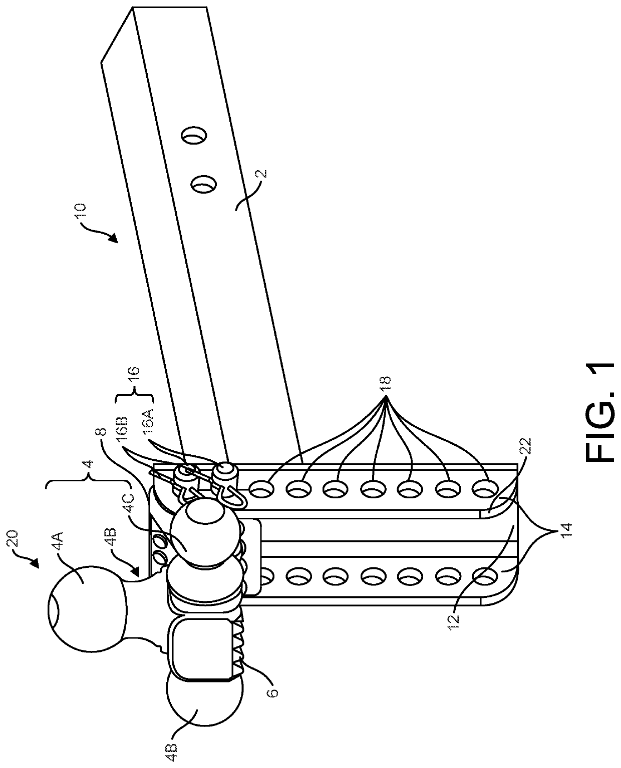
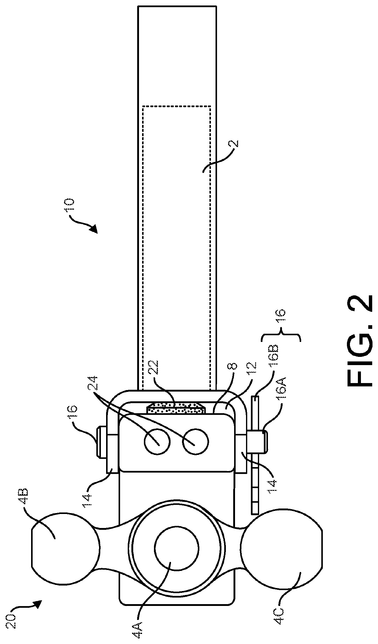
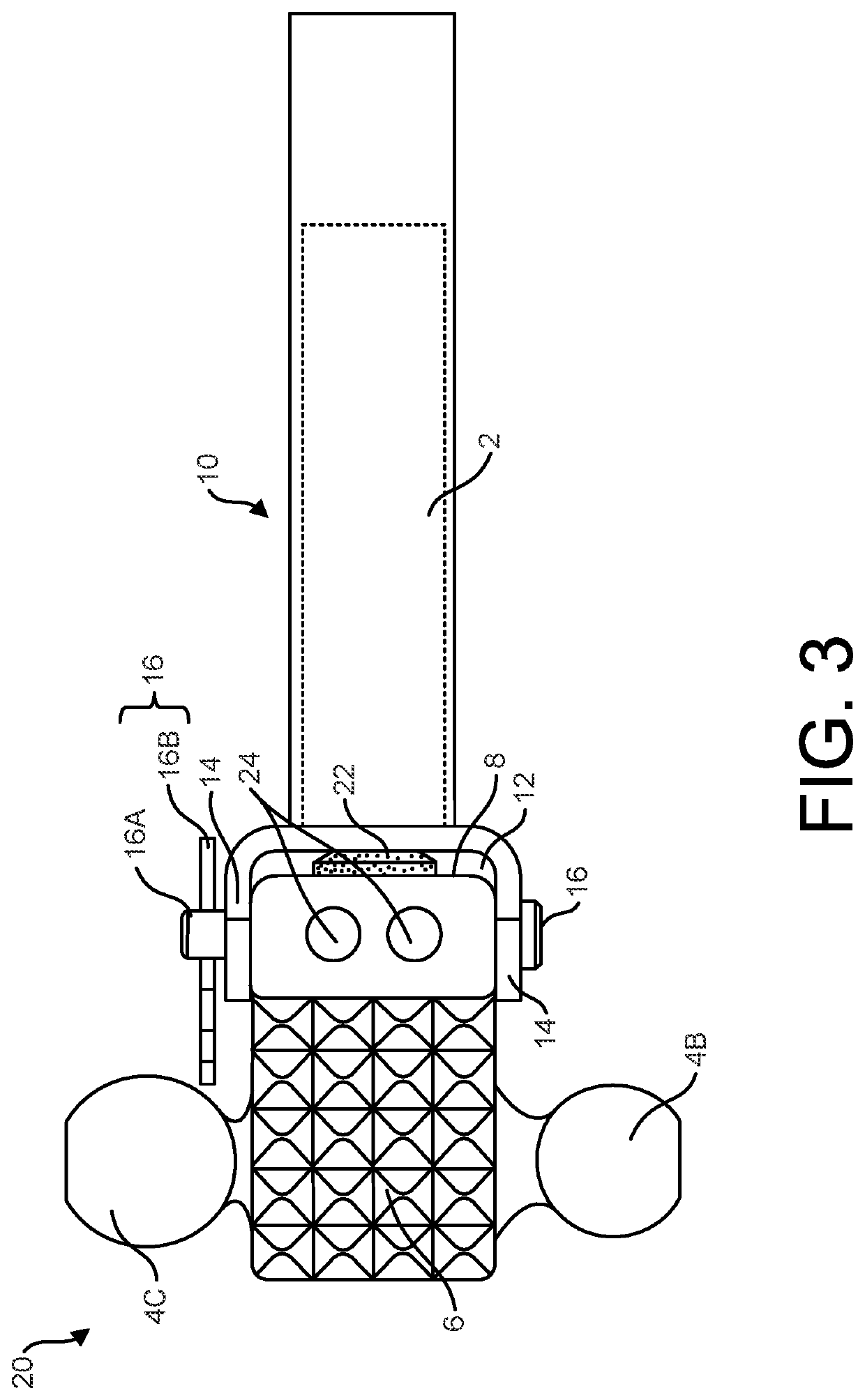
The present invention is a hitch assembly for mounting a tow accessory or trailer to a tow vehicle. It includes a hitch platform, multiple hitch members, and a locking pin. The hitch platform has a shank tube member for telescoped coupling with a receiver tube attached to the tow vehicle, and a channel member with a recessed column and side holes. The multiple hitch members have hitch mounting balls, tow hooks, and a step member. A dampening member is inserted between the base of the tow accessory and the hitch platform to absorb and dampen impacts, reduce vibration, and quiet rattling and swaying. The hitch assembly reduces movement, rub, and associated friction between the hitch platform and the hitch member, and quiets any associated vibration, rattling, and swaying.

Problems solved by technology

A particular problem with the use of these receiver coupling systems is play between the receiver hitch platforms and hitch ball or direct tow accessory assemblies.
The base of the tow mount or accessory tends to rattle or chatter within the channel of the hitch platform.
This rattle or chatter is at best an annoyance and at worst can distract the driver or cause damage to the trailer or the carrier.
Although the latter dual pin mount provided the substantial improvements of reduced play, rattling and pivoting of the hitch assembly relative to the vehicle, movement and vibration due to loosening and play between the tow accessory member and hitch receiver platform persists.
Such movement, vibration and noise is exacerbated if the tow accessory is installed on an upper or lower section of the channel and thus not evenly supported along the base of the tow accessory.
Such eccentric positioning of the hitch ball along the hitch platform channel and resulting movement causes vibrations and gyrating movement.
In extreme driving terrain or weather conditions, even hazardous swaying of the vehicle may result.
However, since the rubber device is installed in the hitch platform, the hitch ball may not align with the rubber device in all positions, particularly when a dual flange ball that is installed on the uppermost or lowermost portion of the platform.
Although the latter device provided an improvement over prior art hitch assemblies and reduced rocking, swaying and pivoting of the hitch assembly relative to the vehicle, issues arising from loose rattling between the tow accessory member and hitch receiver platform persists.
As is readily surmised from consideration of impacts and resulting external forces exerted upon a vehicle and any towed accessory will shake and exert commensurate stress loosening abutting rigid metal surfaces of the hitch assembly and will resonate toward edges of the hitch ball base and platform, resulting in rattling and possible swaying of the vehicle.
Such vibration, noise and directional interference with safely steering the car may be exacerbated if the hitch ball or tow accessory are not tightly compressed along the channel of the platform.
This is particularly problematic if the hitch ball mount tow accessory is installed on an uppermost or lowermost end of the channel where the entire length of the hitch ball mount base is not supported along the channel of the tow accessory, which is a particularly prevalent issue associated with dual flange ball.
When in upper and lower mounted positions, the base may extend beyond the channel and flanges support exacerbating movement causing rattling and vibrations and may even cause veering, swaying, gyrating and even dangerous pivoting to one side or another of the vehicle that is difficult.
This rattle or chatter is at best an annoyance and at worst can distract the driver or cause damage to the vehicle or tow accessory.
In extreme driving terrain or weather condition, the swaying or pivoting of the vehicle may be impossible to control.
The drawbacks of unattenuated rattle or sway may be exacerbated when multi-purpose hitch mounts with more complex structures are used.
The convergence of the load stress on the tow hitch and pin mount thus limit the tolerance levels of conventional tow hitch accessory mounts.
However, drawbacks associated with the bulk and density as well as piecemeal joining, typically by soldering or welding, of corresponding mated surfaces of the each of the three balls as well as the step may compromise the strength and durability of conventional triple ball mounts.
Unfortunately, the impact and torque exerted by the physical load together with the vibration and pressure from the pulling and pushing on the adjoined surfaces and fastener pins of conventional triple ball tow hitch may erode and loosen the adjoined surfaces of components of conventional multiple function hitch mounts thereby compromising their strength, durability and safety.
Moreover, the bulk and density of such multifunctional tow mounts exacerbate the vibrational rattle and sway caused by friction between abutting metal surfaces of the hitch and socket and attachment hardware, such as fastener pins securing a telescoped tow shank into the receiver tube of the towing vehicle.
Yet another disadvantage attendant to conventional mounts for triple ball mounts is the lack of height adaptability.
Thus, although the variously sized balls accommodate different socket sizes of tow accessories, they are not adjustable to the height of a particular trailer or other equipment being towed.
This is a particular problem if the towing vehicle hitch receiver sits relatively low to the ground and alternatively and a relatively high trailer exerts a lifting action on the back end and wheels while the front is pushed downwardly.
In the latter situation, the towed load pressure may even cause gyrations and involuntary directional pulls that could ultimately cause the driver of the towing vehicle to lose control and even result in an accident.

Method used


Image

  • Multiple hitch assembly
  • Multiple hitch assembly
  • Multiple hitch assembly

Examples


Embodiment Construction

[0045]Exemplary embodiments of the present invention illustrated in FIGS. 1-10 depict alternative configurations of the multiple hitch assembly that may include a plurality of hitch balls, tow hooks and a step mount integrally disposed in different directions from a pedestal of a block base having a dampening member affixed to the rear surface such that the dampening member 22, 22′ and 22″ affixed directly to the back surface of a base portion 8, 8′ and 8″ of a dual flange ball tow mount hitch member 20.

[0046]It is to be expressly understood that the illustrative embodiment is a representation of the invention for explanatory purposes only and is not meant to unduly limit the claimed invention. The representative embodiment of the present invention is intended for use with receiver hitch systems including trailer mounts but also includes other dual or triple hitch mount configurations with or without a step hitch member such as detailed below. The illustrated as well as alternative ...


PUM


Abstract

A multiple hitch assembly and method of use thereof including a hitch platform having a channel member and multiple hitch member having a block base. A dampening member may be affixed such that coupling of the multiple hitch member by locked engagement of received through holes of the block base and paired side holes disposed in flanges of the channel member compresses the dampening member upon the recessed column of the hitch platform to absorb and thus attenuate the load and associated torque imparted by movement and rub between the hitch platform and multiple hitch member to thereby reduce associated rattle noise, and vibration.

Description

CROSS-REFERENCE TO RELATED APPLICATIONS[0001]This application claims priority to and benefit under 35 USC § 119(e) of U.S. patent application Ser. No. 16 / 518,471 having a filing date of Jul. 22, 2019, which claims priority to and benefit under U.S. Provisional Patent Application Ser. No. 62 / 711,771 having a filing date of Jul. 30, 2018, which are both hereby incorporated by reference herein.FIELD OF THE INVENTION[0002]This invention relates to the field of tow accessories, particularly a multiple hitch assembly that may include hitch a step hitch member including one or more hitch balls, tow hooks and rings together with a dampening mechanism for reducing the relative movement and rattling between a tow accessory base and hitch receiver.BACKGROUND OF THE INVENTION[0003]Many vehicles today are equipped with receiver-type trailer hitches. These types of trailer hitches typically are a square tube, normally 1¼ or 2″ (3.2 cm or 5 cm) internal height and width, attached to the undercarri...

Claims


Application Information

Patent Timeline
Patent Type & Authority Applications(United States)
IPC IPC(8): B60D1/07B60D1/06B60D1/52B60D1/46B60R3/00B60D1/04
CPCB60D1/07B60D1/065B60D1/04B60D1/46B60R3/007B60D1/52B60D1/06B60D1/241
Inventor SINGH, ARVINDERSINGH, HARDEEPGOOD, JEFF
Owner ADVANCED ENG GRP LLC
Why Eureka
Eureka Blog
Learn More