Eureka AIR delivers breakthrough ideas for toughest innovation challenges, trusted by R&D personnel around the world.

LED based display panel including common LED driving circuit and display apparatus including the same

a technology of led driving circuit and display panel, which is applied in the direction of electrical equipment, semiconductor devices, instruments, etc., can solve the problems of increasing instantaneous power supplied to the display apparatus, and achieve the effect of reducing instantaneous power and average power consumed, and reducing manufacturing costs

Active Publication Date: 2021-08-05
SAMSUNG ELECTRONICS CO LTD
View PDF9 Cites 6 Cited by
  • Summary
  • Abstract
  • Description
  • Claims
  • Application Information

AI Technical Summary

Benefits of technology

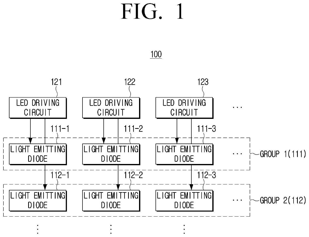
The patent is about a display panel that reduces the power consumption and manufacturing cost by dividing the emission periods of multiple light-emitting diodes into groups and using one LED driving circuit to drive multiple diodes. This reduces the instantaneous power and average power of the display, and makes it more efficient. The panel can also be advantageous in terms of space utilization. Overall, the technical effects are reduced power consumption, lower manufacturing cost, and improved efficiency of the display panel.

Problems solved by technology

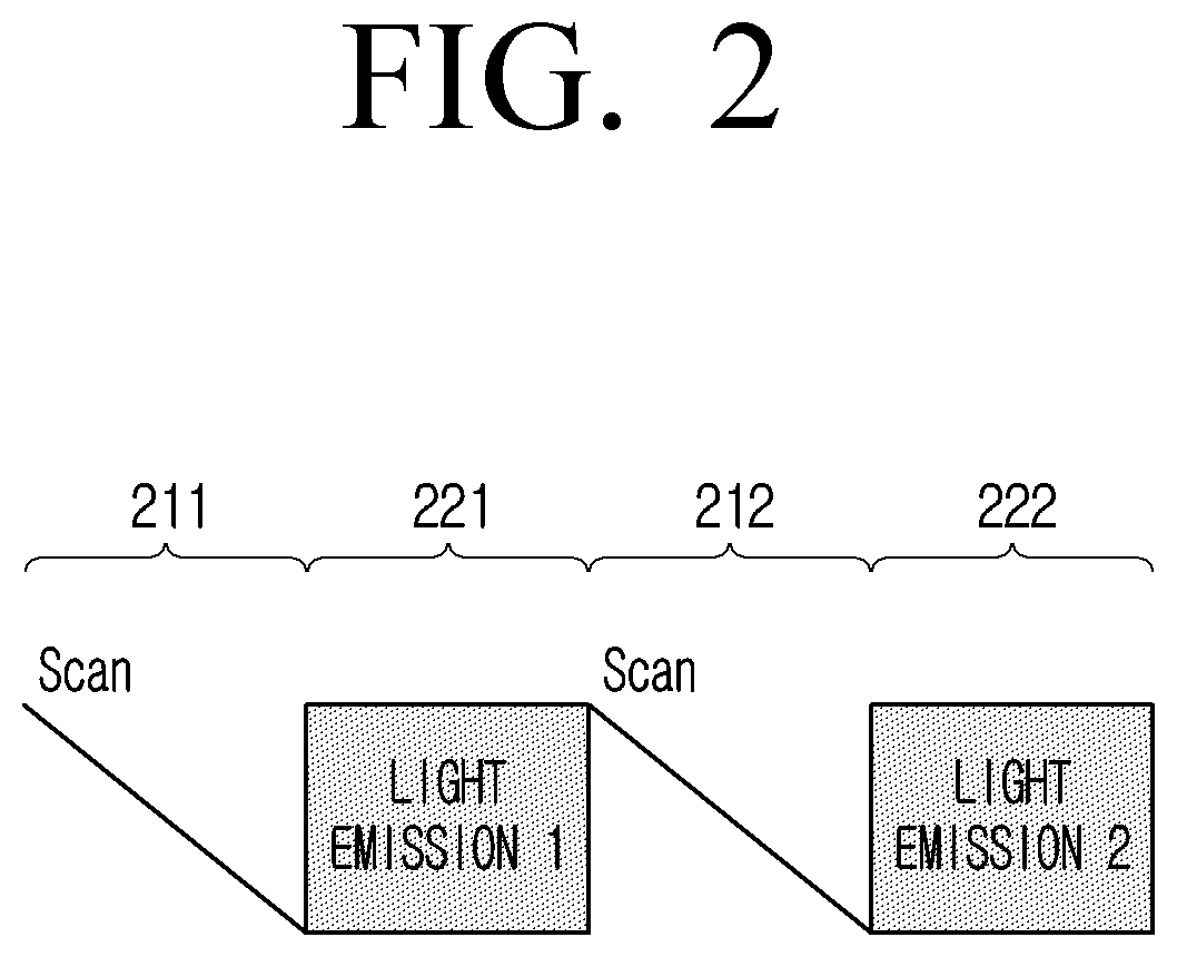
However, there is a problem in that instantaneous power supplied to the display apparatus increases as the light emission of the light-emitting diode is concentrated only in a specific period.

Method used


Image

  • LED based display panel including common LED driving circuit and display apparatus including the same
  • LED based display panel including common LED driving circuit and display apparatus including the same
  • LED based display panel including common LED driving circuit and display apparatus including the same

Examples


Embodiment Construction

[0038]In the following description, a detailed description of the related art or well-known functions may not be described in detail if they would obscure the gist of the disclosure with unnecessary details. In addition, redundant description of the embodiments will be omitted.

[0039]The terms used in the following description are provided to explain example embodiments and are not intended to limit the scope of the disclosure. Singular forms may include plural forms, unless the context clearly indicates otherwise.

[0040]Throughout the disclosure, it will be understood that the term “comprise” and variations thereof, such as “comprising” and “comprises”, specify the presence of features, numbers, steps, operations, components, parts, or combinations thereof, but do not preclude the presence or addition of one or more other features, numbers, steps, operations, components, parts, or combinations thereof.

[0041]In the description, the terms “first, second, and so forth” are used to descr...


PUM

PropertyMeasurementUnit
pulse width modulationaaaaaaaaaa
voltageaaaaaaaaaa
drive currentaaaaaaaaaa

Abstract

A display panel is provided. The display panel includes a plurality of light-emitting diodes constituting a plurality of sub-pixels of the display panel and configured to be divided into a plurality of groups; and a plurality of LED driving circuits configured to: receive a PWM data voltage in a scanning period; and based on the PWM data voltage, drive the plurality of light-emitting diodes by providing drive current to the plurality of light-emitting diodes for a time corresponding to the PWM data voltage in an emission period, wherein each of the plurality of LED driving circuits is configured to be connected to light-emitting diodes included in respective groups of the plurality of groups, and drive the light-emitting diodes of the respective groups.

Description

CROSS-REFERENCE TO RELATED APPLICATION[0001]This application is based on and claims priority under 35 U.S.C. § 119(a) to Korean Patent Application No. 10-2020-0013979, filed on Feb. 5, 2020 in the Korean Intellectual Property Office, the disclosure of which is incorporated by reference herein in its entirety.BACKGROUND1. Field[0002]The disclosure relates to a light-emitting diode-based display panel and a display apparatus including the same. More specifically, the display apparatus relates to a connection and operation of a light-emitting diode (LED) driving circuit for driving the LED constituting a sub-pixel.2. Description of Related Art[0003]A pulse amplitude modulation (PAM) that expresses a grayscale (or gradation) with a difference in voltage applied to a light-emitting diode and / or a pulse width modulation (PWM) that expresses the grayscale with a difference in time when voltage is applied to the light-emitting diode have been used as a method of adjusting the grayscale of l...

Claims


Application Information

Patent Timeline
Patent Type & Authority Applications(United States)
IPC IPC(8): G09G3/32H01L27/15
CPCG09G3/32G09G2310/0275H01L27/156H01L25/167H01L33/62H01L25/0753G09G2330/021G09G3/3233G09G3/3266G09G3/3275G09G2300/0426G09G2300/0804G09G2300/0819G09G2300/0861G09G2300/0852G09G2310/0224G09G2310/0218G09G3/2007
Inventor JUNG, YOUNGKISHIGETA, TETSUYAKIM, JINHOJUNG, CHULGYU
Owner SAMSUNG ELECTRONICS CO LTD
Why Eureka
Eureka Blog
Learn More