Array ultrasonic instrument test platform and method

An ultrasonic instrument and testing platform technology, applied in instruments, scientific instruments, material analysis using sound waves/ultrasonic waves/infrasonic waves, etc., can solve problems such as interface damage and heavy workload, reduce signal attenuation and distortion, and ensure safety , the effect of accurate test accuracy

Pending Publication Date: 2022-08-09
INST OF ACOUSTICS CHINESE ACAD OF SCI
View PDF1 Cites 0 Cited by
  • Summary
  • Abstract
  • Description
  • Claims
  • Application Information

AI Technical Summary

Problems solved by technology

[0006] The purpose of the present invention is to overcome the existing manual method for testing array ultrasonic instruments, which requires a huge workload an

Method used


Image

  • Array ultrasonic instrument test platform and method
  • Array ultrasonic instrument test platform and method
  • Array ultrasonic instrument test platform and method

Examples


Example Embodiment

[0040] Example 1

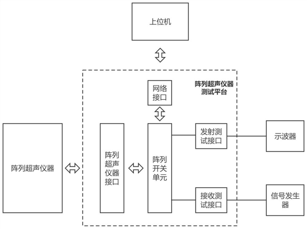
[0041] In this embodiment, the array ultrasonic instrument includes 128 channels, such as Figure 1-2 As shown in the figure, the 128-channel ultrasonic instrument signal of the array ultrasonic instrument is switched to 2 test channels (one transmitting and one receiving) at the other end. After equipped with standard instruments such as signal generator and oscilloscope, it can meet the testing requirements of the array ultrasonic instrument. For example, switch the channel N of the ultrasound instrument to the transmit test channel, and match the transmit parameters (transmit voltage, pulse edge time, transmit output impedance, etc.) of the oscilloscope test channel N; switch the channel N of the ultrasound instrument to the receive test channel, and match the signal The generator tests channel N's receive parameters (bandwidth, equivalent input noise, vertical linearity, etc.).

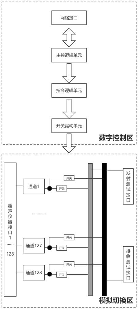
[0042] An implementation of the present invention is as follows: figure ...

Example Embodiment

[0071] Example 2

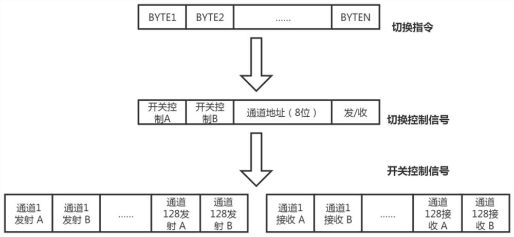
[0072] When the ultrasonic channel of the array ultrasonic instrument works in the transmitting state, there will be high-voltage pulses (the pulse voltage is usually above 100 volts). In order to ensure that the switching of the test platform does not damage the ultrasonic instrument, the Figure 4 The switching logic shown, the system enters the reset state after power-on, and switches the 128 ultrasonic channels to the state where they are not connected to the transmit test channel and the receive test channel in turn; then wait for the transmit and receive switching instructions to be obtained and parsed. Switch the ultrasonic channel in the previous "transmission switching command" to the disconnected state, save the current "transmission switching command", connect the ultrasonic channel in the current "transmission switching command" to the transmission test channel, and put the previous "receive switching command" The ultrasonic channel in the switch...


PUM

PropertyMeasurementUnit
Characteristic impedanceaaaaaaaaaa

Abstract

The invention relates to the field of ultrasonic nondestructive testing instruments, in particular to an array ultrasonic instrument testing platform and method. The test platform comprises a relay array, an upper computer and a control module, and the relay array comprises a plurality of transmitting test relays and a plurality of receiving test relays; the emission test relay is used for connecting the electric connection between the ultrasonic channel and the emission test interface when the emission signal of the ultrasonic channel is tested based on the control of the control module; the electric switch is also used for disconnecting the electric connection between the ultrasonic channel and the emission test interface when the test is finished; the receiving test relay is used for connecting the electrical connection between the ultrasonic channel and the receiving test interface when the receiving signal of the ultrasonic channel is tested based on the control of the control module; the electric switch is also used for disconnecting the electric connection between the ultrasonic channel and the receiving test interface when the test is finished; according to the invention, automatic testing is realized, and the testing efficiency is improved.

Description

technical field [0001] The invention relates to the field of ultrasonic nondestructive testing instruments, in particular to an array ultrasonic instrument testing platform and method. Background technique [0002] As a convenient, fast, accurate and non-destructive testing method, ultrasonic non-destructive testing method is of great significance in national production and life. With the rapid development of electronic technology, the mechanical structure of the inspected workpiece is becoming more and more complex, and the application of array ultrasonic instruments in ultrasonic nondestructive testing is becoming more and more common, such as multi-channel ultrasonic instruments, phased array ultrasonic instruments, full matrix capture (FMC) calculation Imaging ultrasound equipment and more. According to the application requirements, the number of channels of the array ultrasonic instrument is 8, 16, 32, 64, 128, 256, etc. When multiple instruments work in combination, i...

Claims


Application Information

Patent Timeline
IPC IPC(8): G01N29/30G05B19/042
CPCG01N29/30G05B19/0423
Inventor 冷涛
Owner INST OF ACOUSTICS CHINESE ACAD OF SCI
Why Eureka
Try Eureka