Polygonal spherical space sampling device

a sampling device and polygonal spherical technology, applied in the direction of resistance/reactance/impedence, magnetic/electric field screening, instruments, etc., can solve the problems of inaccurate test, impaired reference value, and unsatisfactory test efficiency

Active Publication Date: 2022-09-13
SHENZHEN XINYI TECH CO LTD
View PDF11 Cites 0 Cited by
  • Summary
  • Abstract
  • Description
  • Claims
  • Application Information

AI Technical Summary

Benefits of technology

[0027]1. a turntable structure in a common sampling device is eliminated, after the object to be tested is placed on the supporting platform 3, the object to be tested is in a static state; when the sampling data of the object to be tested needs to be measured omnidirectionally, the object to be tested is always in a static state, since the plurality of probes 1 are distributed in a three-dimensional spherical space, the probe at each point is activated by electrically controlled switching, there is no mechanical rotation of a turntable, the test efficiency is higher, and the present application is more suitable for the rapid measurement requirement of the production line;
[0028]2. when different objects to be measured are tested, test jigs with different heights or the supporting plate with adjustable heights both ensures that the object to be tested is at the center of the three-dimensional spherical space during testing, and the applicability of the device is higher, and the test precision is more accurate.

Problems solved by technology

The spatial sampling technology is a key technology for spherical near-field measurement, and the accuracy of sampling data directly affects the field transformation result of electromagnetic waves, which is a key factor for influencing system errors.
It is found that the prior art suffers from at least the following defects: the turntable is rotated mechanically, one mechanical rotation needs to be performed for each test, to drive the object to be tested to rotate by an angle, and the test efficiency is not ideal.
Furthermore, the turntable serves as an arbitrarily movable component, the rotation precision of the turntable has a large uncertainty, therefore, the test precision of the whole sampling device is not affected by the rotation precision of the turntable, and the test precision is higher.
If the topmost and bottommost of the three-dimensional spherical space are not provided with a probe, during testing, representative key data at the two points will be missing, which results in inaccurate test results and impaired reference value.

Method used


Image

  • Polygonal spherical space sampling device
  • Polygonal spherical space sampling device
  • Polygonal spherical space sampling device

Examples


embodiment 1

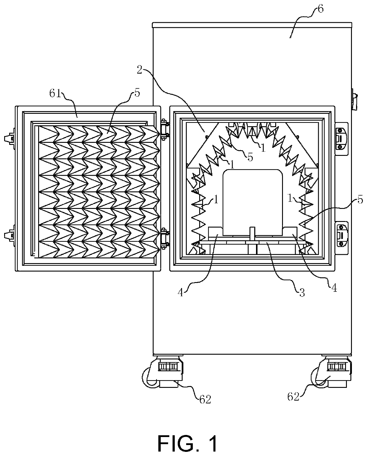
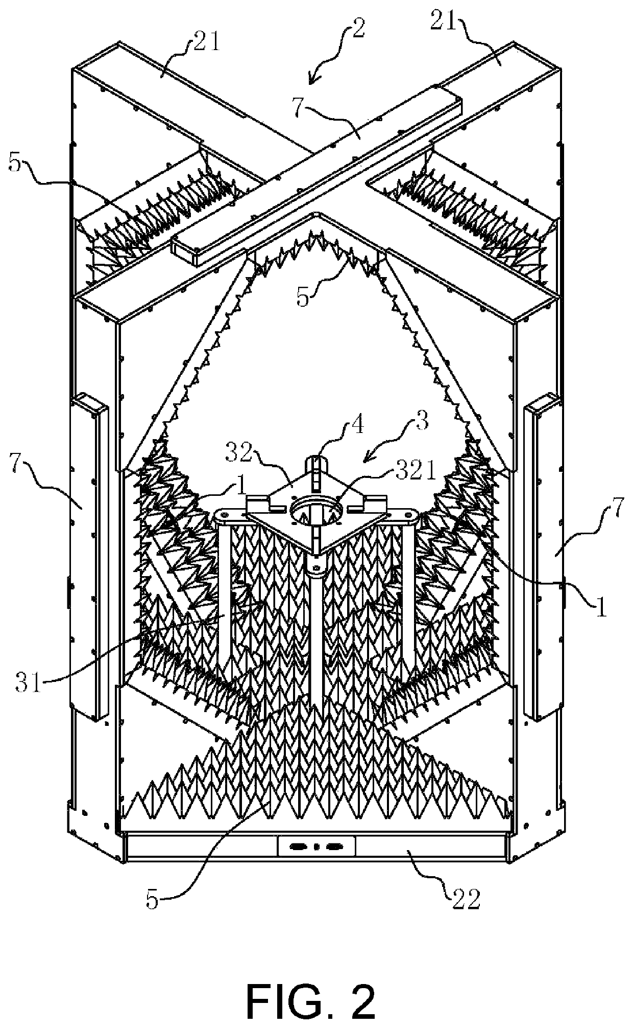
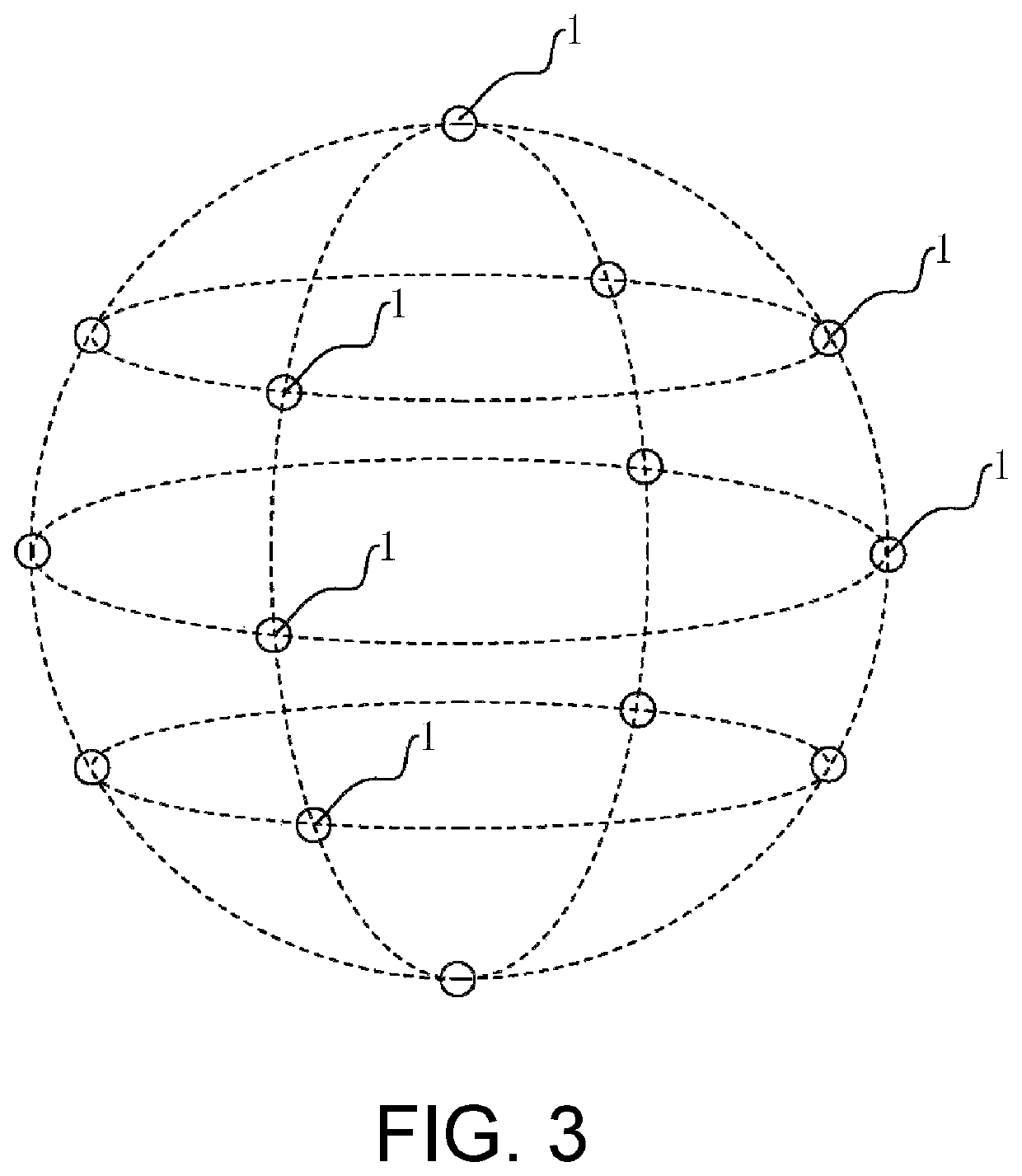
[0037]Referring to FIGS. 1 and 2, the mounting rack 2 of a polygonal spherical space sampling device includes two mounting frames 21 arranged perpendicular to one another and a base 22. The two mounting frames 21 are both perpendicular to an upper surface of the base 22 (in other embodiments, the mounting frames 21 may be arranged horizontally, but the base 22 may be replaced by a vertical square frame), the A is 45, the B is 90, the number of the probes 1 is equal to fourteen, the arrangement of the fourteen probes 1 in a three-dimensional spherical space is shown in detail in FIG. 3, a junction joint at the top of the two mounting frames 21 and a junction joint at the bottom of the two mounting frames 21 respectively share one of the probes 1.

[0038]The supporting platform 3 includes a connecting portion 31 and a supporting plate 32, the supporting plate 32 is fixed to the mounting rack 2 through the connecting portion 31, and the supporting plate 32 is provided with a weight reduc...

embodiment 2

[0047]Referring to FIGS. 2 and 4, a polygonal spherical space sampling device differs from the Embodiment 1 in that: the mounting rack 2 includes a base 22 and three mounting frames 21 arranged symmetrically around a vertical axis, the three mounting frames 21 are perpendicular to an upper surface of the base 22 (not shown in the drawings of the present application, however, the structures of the three mounting frames 21 are consistent with those in FIG. 2. and the angle between the three mounting frames 21 is 60 degrees), the A is 45, the B is 60, the number of the probes is equal to twenty, the arrangement of the twenty probes 1 in a three-dimensional spherical space is shown in detail in FIG. 4, a junction joint at the top of the three mounting frames 21 and a junction joint at the bottom of the three mounting frames 21 respectively share one of the probes 1.

[0048]The probes 1 are distributed more densely and uniformly, the number of the test points is relatively large, and the t...

embodiment 3

[0049]Referring to FIGS. 2 and 5, a polygonal spherical space sampling device differs from the Embodiment 1 in that: the mounting rack 2 includes two mounting frames 21 arranged perpendicular to one another and a base 22; the two mounting frames 21 are both perpendicular to an upper surface of the base 22 (not shown in the drawings of the present application, however, the structures of the two mounting frames 21 are consistent with those in FIG. 2), both A and B are equal to 90, the number of the probes is equal to six, the arrangement of the six probes 1 in a three-dimensional spherical space is shown in detail in FIG. 5, a junction joint at the top of the two mounting frames 21 and a junction joint at the bottom of the two mounting frames 21 respectively share one of the probes 1.

[0050]The probes 1 are distributed in such a way that the number of the probes 1 is minimum while the manufacturing cost of the entire device is the lowest.


PUM


Abstract

This application provides a polygonal spherical sampling device, belonging to the technical field of spherical field antenna measurement, and including a probe, a mounting rack and a supporting platform. The supporting platform is mounted on the mounting rack for placing an object to be tested. The number of the probes is more than or equal to six, the probes are mounted on the mounting rack and a plurality of the probes are distributed on at least two vertical planes in a three-dimensional spherical space and are arranged around the supporting platform. The vertical planes are arranged symmetrically about a vertical axis, the probes are uniformly distributed at intervals of A degrees on each vertical plane, the probes on a same horizontal plane are uniformly distributed at intervals of B degrees, both A and B are less than or equal to 90.

Description

CROSS-REFERENCE TO RELATED APPLICATION[0001]The present application is based on and claims the priority benefits of China application No. 202011455911.5, filed on Dec. 10, 2020. The entirety of the above-mentioned patent application is hereby incorporated by reference herein and made a part of this specification.BACKGROUNDTechnical Field[0002]The present application relates to the technical field of spherical field antenna measurement, and more particularly to a polygonal spherical sampling device.Description of Related Art[0003]Near-field measurement refers to recording the relationship between the amplitude of a voltage received by the probe with known electrical characteristics, and the phase change along with position on a surface of a near area, at a distance of 3-8 wavelengths from the antenna, and determining the far-field characteristic of the antenna by strictly near-to-far-field mathematical transformation. Depending on shapes of the scanning surface, near-field measuremen...

Claims


Application Information

Patent Timeline
Patent Type & Authority Patents(United States)
IPC IPC(8): G01R27/28G01R29/10H05K9/00
CPCG01R29/105H05K9/0009G01R29/10G01R29/0871
Inventor CHEN, LINBINXIE, ZHENKUNWANG, DAOYISUN, CIENJIANG, KAIXUAN
Owner SHENZHEN XINYI TECH CO LTD
Why Eureka
Try Eureka