Electric power steering device

a technology of electric power steering and steering wheel, which is applied in the direction of electric steering, power driven steering, vehicle components, etc., can solve the problems of driving discomfort and stress, and achieve the effects of reducing steering discomfort, increasing steering force, and preventing excessive compensation

Active Publication Date: 2021-08-12
NSK LTD
View PDF0 Cites 6 Cited by
  • Summary
  • Abstract
  • Description
  • Claims
  • Application Information

AI Technical Summary

Benefits of technology

[0025]The electric power steering device according to the present invention has an advantage that the assist force is increased, and thus the steering can be performed up to the physical rack end or a close distance thereof, and the turning radius of the vehicle steering is not affected, since the rack end control output (reaction force) is reduced in the vicinity of a virtual rack end, even when a control system is constructed based on a physical model, the displacement input to the viscoelastic model is adjusted based on steering torque and SAT, and the end-abutting impact mitigation control unit is provided. In particular, the control steering angle shifting unit is provided with a limiter that limits the shift steering angle amount in a predetermined area, thereby preventing excessive compensation, reducing steering discomfort, and preventing the occurrence of rack-end impact noise.

Problems solved by technology

In the electric power steering device as described above, when a large assist torque is added by the motor in the vicinity of a maximum steering angle (rack end) of the steering system, there is a possibility that a large impact occurs and a hit sound (abnormal noise) is generated at a time point when the steering system has reached the maximum steering angle, which causes a driver to feel uncomfortable and to be subjected to stress.

Method used


Image

  • Electric power steering device
  • Electric power steering device
  • Electric power steering device

Examples


first embodiment

[0077]In the configuration as described above, an operation example thereof (first embodiment) will be described with reference to a flowchart in FIG. 14.

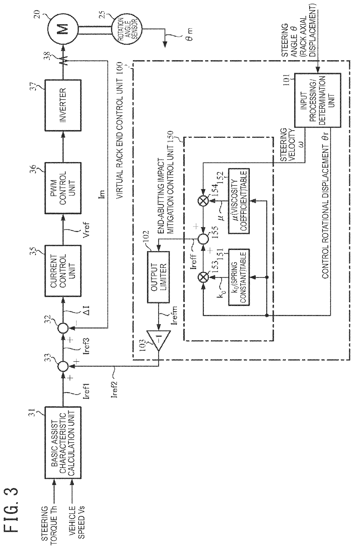
[0078]First, steering torque Th, vehicle speed Vs, and steering angle θ are input (step S1), and a current command value Iref1 is calculated in a basic assist characteristic calculation unit 31 (step S2). The input processing / determination unit 101 calculates and outputs a steering velocity ω and a control rotational displacement θr, based on the steering angle θ (step S3). The steering velocity ω is input to the subtraction unit 124A-4 in the control steering angle shifting unit 120 and the multiplication unit 154 in the end-abutting impact mitigation control unit 150, and the control rotational displacement θr is input to the sign determination unit 126 in the control steering angle shifting unit 120 and, in conjunction therewith, input to the subtraction unit 122 as a positive input. The sign determination unit 126 determines a ...

eleventh embodiment

[0093]FIG. 28A is a block diagram illustrative of a configuration example of a control steering angle shifting unit 120 of an The control steering angle shifting unit 120 may determine a correction gain G, based on a multiplication result (Th×SN) of steering torque Th and a sign SN and calculate a control rotational displacement θr corrected by the correction gain G as a shift control steering angle θrs.

[0094]The control steering angle shifting unit 120 of the eleventh embodiment includes a multiplication unit 124C-1 configured to multiply the steering torque Th by the sign SN, a gain setting unit 124C-2 configured to set gain G in accordance with characteristics as illustrated in FIG. 28B according to a multiplication result (Th×SN) by the multiplication unit 124C-1, and a multiplication unit 124C-3 configured to calculate a shift control steering angle θrs by multiplying the gain G by the control rotational displacement θr. As with the other embodiments, the control steering angl...


PUM


Abstract

An electric power steering device including: a control rotational displacement calculation unit configured to calculate a control rotational displacement when a steering angle of the steering system is in an angular range from a maximum allowable steering angle for the steering system to a predetermined threshold steering angle; a control steering angle shifting unit configured to calculate the control rotational displacement corrected by a correction amount based on one of the steering torque and rack axial force and a sign of one of the control rotational displacement and the steering angle as a shift control steering angle; and a feedforward control unit configured to output a second current command value based on the shift control steering angle and steering velocity. An assist control is controlled with a third current command value calculated by adding the second current command value to the first current command value.

Description

TECHNICAL FIELD[0001]The present invention relates an electric power steering device that calculates a current command value, based on at least steering torque, drives a motor by means of the current command value, and provides a steering system of a vehicle with assist force and, in conjunction therewith, in order to suppress impact and hit sound (abnormal noise) at the time of rack end end-abutting, by reducing the assist force and increasing reaction force, forms a virtual rack end, and, in particular, relates to a high-performance electric power steering device that, by reducing rack end control output (reaction force) in the vicinity of the virtual rack end located before a physical rack end and thereby increasing the assist force, enables a driver to turn the steering wheel to the rack end without stress and does not influence the turning radius of a vehicle.BACKGROUND ART[0002]Electric power steering devices (EPS) that provide a steering system of a vehicle with assist force,...

Claims


Application Information

Patent Timeline
Patent Type & Authority Applications(United States)
IPC IPC(8): B62D5/04
CPCB62D5/0463B62D6/00B62D5/0469B62D6/008B60Y2400/307
Inventor KITAZUME, TETSUYAMARUYAMA, SHOYA
Owner NSK LTD
Why Eureka
Try Eureka