Method for densifying porous annular substrates by chemical vapour infiltration

Active Publication Date: 2021-08-12
SAFRAN CERAMICS
View PDF1 Cites 0 Cited by
  • Summary
  • Abstract
  • Description
  • Claims
  • Application Information

AI Technical Summary

Benefits of technology

[0009]Each stack of unit modules thus produced defines a central duct formed by the joining of the internal volumes of the stacks of substrates (said volumes communicate through the central openings of the support plates), and a peripheral duct formed by the joining of the external volumes to the stacks of substrates located inside the unit modules (said volumes communicate through the outlet openings of the support plates). The central duct allows the injected gas to be conveyed inside the stack and over its entire height, while the peripheral duct has the function of recovering and channelling the precursor gas that has passed through the substrates in order to discharge it. The peripheral duct thus defined channels the gases that have not reacted more quickly for their discharge, for example at the level of an outlet opening present in an upper wall of the chamber, which limits their maturation time and reduces the quantity of polycyclic hydrocarbons (PAH) produced per kilogram of carbon deposited within the substrates.
[0010]Moreover, the cylinders of each unit module form thermal masses as close as possible to the stacks of substrates, which reduces temperature gradients within the chamber and improves the homogeneity and densification kinetics of the substrates. The reducti

Problems solved by technology

Such loading has several drawbacks: it is long and complex to perform, temperature gradients may be present within the chamber, and seals between the support plates and stack sections are difficult to guara

Method used


Image

  • Method for densifying porous annular substrates by chemical vapour infiltration
  • Method for densifying porous annular substrates by chemical vapour infiltration
  • Method for densifying porous annular substrates by chemical vapour infiltration

Examples


Embodiment Construction

[0029]A chemical vapour infiltration densification process according to the invention comprises, first, a step during which a plurality of unit modules 10 are provided (FIGS. 5 and 6).

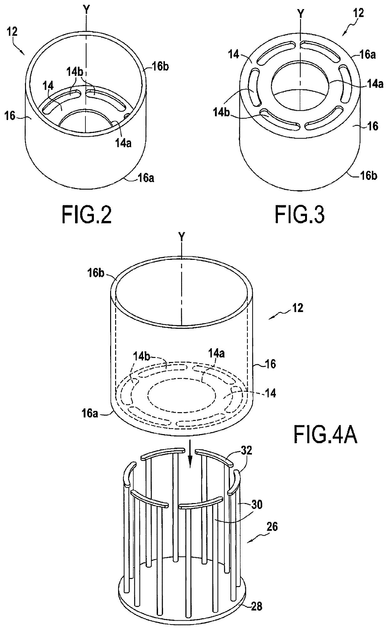
[0030]A unit module 10 first comprises a structural part 12 (FIGS. 2 and 3) comprising a support plate 14 with a central gas inlet opening 14a and gas outlet openings 14b distributed angularly around the central opening 14a. The support plate 14 is here in the form of an openwork disc. The gas outlet openings 14b form a crown around the central gas inlet opening 14a, i.e., they describe a circle around the central gas inlet opening 14a. The support plate 14 here has six gas outlet openings 14b. The structural part 12 further comprises a cylinder 16 that extends vertically from the support plate 14 and is integral therewith. The cylinder 16 thus comprises a first end 16a integral with the support plate 14, and a second free end 16b. The support plate 14 and the cylinder 16 are centred on an axis Y. The ...


PUM

PropertyMeasurementUnit
Fractionaaaaaaaaaa
Fractionaaaaaaaaaa
Timeaaaaaaaaaa

Abstract

A process for densifying annular porous substrates by chemical vapour infiltration, includes providing a plurality of unit modules including a support plate on which is formed a stack of substrates, the support plate including a central gas inlet opening communicating with an internal volume formed by the central passages of the stacked substrates and gas outlet openings distributed angularly around the central opening, and a thermal mass cylinder disposed around the stack of substrates having a first end integral with the support plate and a second free end, forming stacks of unit modules in the chamber of a densification furnace, and injecting into the stacks of unit modules a gas phase including a gas precursor of a matrix material to be deposited within the porosity of the substrates.

Description

BACKGROUND OF THE INVENTION[0001]The present invention relates to the general field of processes for densifying annular porous substrates by chemical vapour infiltration (CVI). In order to densify such substrates, processes are known in particular in which stacks of substrates are placed in the heated chamber of a densification installation, and a gas phase comprising a matrix material precursor is introduced into the interior of the stacks of substrates so as to form the matrix in the porosity of the substrates. The document FR 2834713 describes such a process and an installation for its implementation.[0002]When a large number of substrate stacks are to be densified, a larger installation is usually used. A known example of a load that can be used in the chamber 1 of a densification furnace is shown in FIG. 1. The chamber 1 is cylindrical around an axis X. The load consists of a plurality of stacks of annular porous substrates 2 carried by a single lower support plate 3. Each stac...

Claims


Application Information

Patent Timeline
IPC IPC(8): C23C16/04C23C16/46
CPCC23C16/045C23C16/46C04B35/83C23C16/455C23C16/4583
Inventor LAMOUROUX, FRANCKDUPONT, RÉMYROS, WILLIAM
Owner SAFRAN CERAMICS
Why Eureka
Try Eureka