
Method for determining the road temperature from inside a motor vehicle

Pending Publication Date: 2021-08-19
HELLA KG HUECK & CO
View PDF4 Cites 0 Cited by
  • Summary
  • Abstract
  • Description
  • Claims
  • Application Information

AI Technical Summary

Benefits of technology

This patent describes a method for accurately measuring the brightness of an vehicle's surrounding environment by using a light sensor that captures the brightness of the sky without being affected by shadowing caused by the vehicle body. The sensor is placed close to the foot of a rear view mirror, which ensures accurate and space-saving placement. The technical effect of this patent is to provide a more accurate measure of the vehicle's surrounding environment, which can aid in driving safely and efficiently.

Problems solved by technology

Moreover, in the event of road surface temperatures below the dewpoint, moisture can condense on the road surface and consequently be deposited on the road.
Moisture films on the road can significantly reduce the effective static friction of the tyre on the road surface and thus impair various functions of the motor vehicle's driving dynamics.
In this context, temperature fluctuations in the road surface temperature around freezing point are to be considered particularly critical, since it is here that there is a danger of black ice.
One of the difficulties encountered when determining the road surface temperature is that it is not sufficiently correlated with ambient temperature, since in certain special situations, e.g., between rows of buildings, or on or under bridges, these two temperature values can differ from each other substantially.
Consequently it is not possible to determine the road surface temperature with a simple measurement of the ambient temperature.
However, these are only able to perform local measurements for a small number of road sections which are equipped with the measuring devices.

Method used


Image

  • Method for determining the road temperature from inside a motor vehicle

Examples


Embodiment Construction

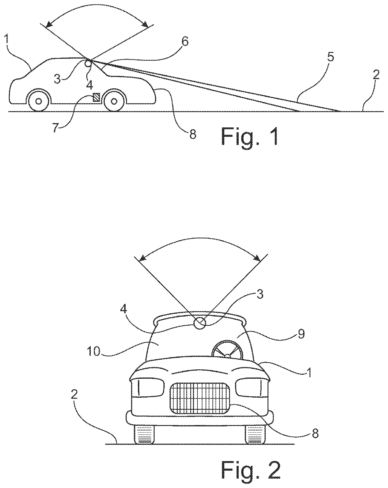
[0033]FIG. 1 shows a motor vehicle 1 which is travelling on a road 2. The motor vehicle 1 is equipped with a light sensor 3 for capturing ambient brightness, that is to say the intensity of the ambient light. The light sensor 3 is arranged to face towards the sky, so that there is an unobstructed optical pathway to the sky. The motor vehicle is further equipped with a light sensor 4 which is designed to capture the radiated light 5 reflected from the road 2. In particular, the light sensor 4 is designed to capture the infrared light component of the reflected radiated light 5. The light sensors 3 and 4 are arranged on the inside of the windscreen 6 of the motor vehicle 1 and might be photodiodes. The motor vehicle 1 is further equipped with at least one moisture sensor 7 for detecting the moisture present on the road 2. The moisture sensor 7 may be a structure borne sound sensor, detecting thrown up moisture droplets. An ambient temperature sensor 8 is arranged close to the air inta...


PUM


Abstract

In a method for determining the surface temperature of a road on which a motor vehicle is travelling, the brightness of the ambient light around the motor vehicle is determined, that radiated light reflected from the road is captured, and that the measured values for brightness of the ambient light and the radiated light reflected from the road are included in the calculation. Also, a sensor arrangement for a motor vehicle for determining the surface temperature of a road on which the motor vehicle is travelling is used to carry out the method, in which at least one light sensor is assigned to the sensor arrangement for capturing the brightness of the ambient light around the motor vehicle, that at least one light sensor is assigned to the sensor arrangement for capturing the radiated light reflected from the road on which the vehicle is travelling.

Description

BACKGROUND OF THE INVENTIONField of the Invention[0001]The invention relates to a method for determining the surface temperature of a road on which a vehicle is travelling. The invention further relates to a sensor apparatus for a vehicle for determining the surface temperature of a road on which a vehicle in travelling, in particular for performing the method according to the invention, wherein at least one light sensor is assigned to the sensor arrangement to capture the brightness of the ambient light around the vehicle.Description of Related Art[0002]In order to drive a motor vehicle in particular a motor vehicle safely, information about the condition of the road on which the vehicle is travelling is of great importance. In particular, the surface temperature of the road is one of the critical influencing factors that affects the force flow reserve between the tyres and the road. A warmer road surface affords a vehicle tyre more grip than a cold road surface. Moreover, in the e...

Claims


Application Information

Patent Timeline
IPC IPC(8): B60W40/06G06V10/60
CPCB60W40/06B60W2400/00B60W2555/20B60W2420/40G06V20/56G06V10/60
Inventor NIEMANN, THOMASKANNING, BASTIAN
Owner HELLA KG HUECK & CO
Learn More