Array substrate and light field display device

Active Publication Date: 2021-08-26
BOE TECH GRP CO LTD
View PDF0 Cites 0 Cited by
  • Summary
  • Abstract
  • Description
  • Claims
  • Application Information

AI Technical Summary

Benefits of technology

[0004]The present disclosure aims to solve or alleviate at least some of the technical problems existing in the prior art. To that end, embodiments of an array su

Problems solved by technology

However, in current light field display devices, each light-emitting point is associated with a large number of signal lines, which makes it di

Method used


Image

  • Array substrate and light field display device
  • Array substrate and light field display device
  • Array substrate and light field display device

Examples


Embodiment Construction

[0024]The following description relates to an array substrate, or display, and a light field display device having the array substrate. The specific embodiments of the present invention will be described in detail below with reference to the accompanying figures. It is to be understood that the specific embodiments described herein are merely illustrative and not restrictive.

[0025]At least in part to improve a density distribution, or pixel resolution, of light-emitting points in the light field display device, the present disclosure provides the array substrate, which will be described below with reference to accompanying figures.

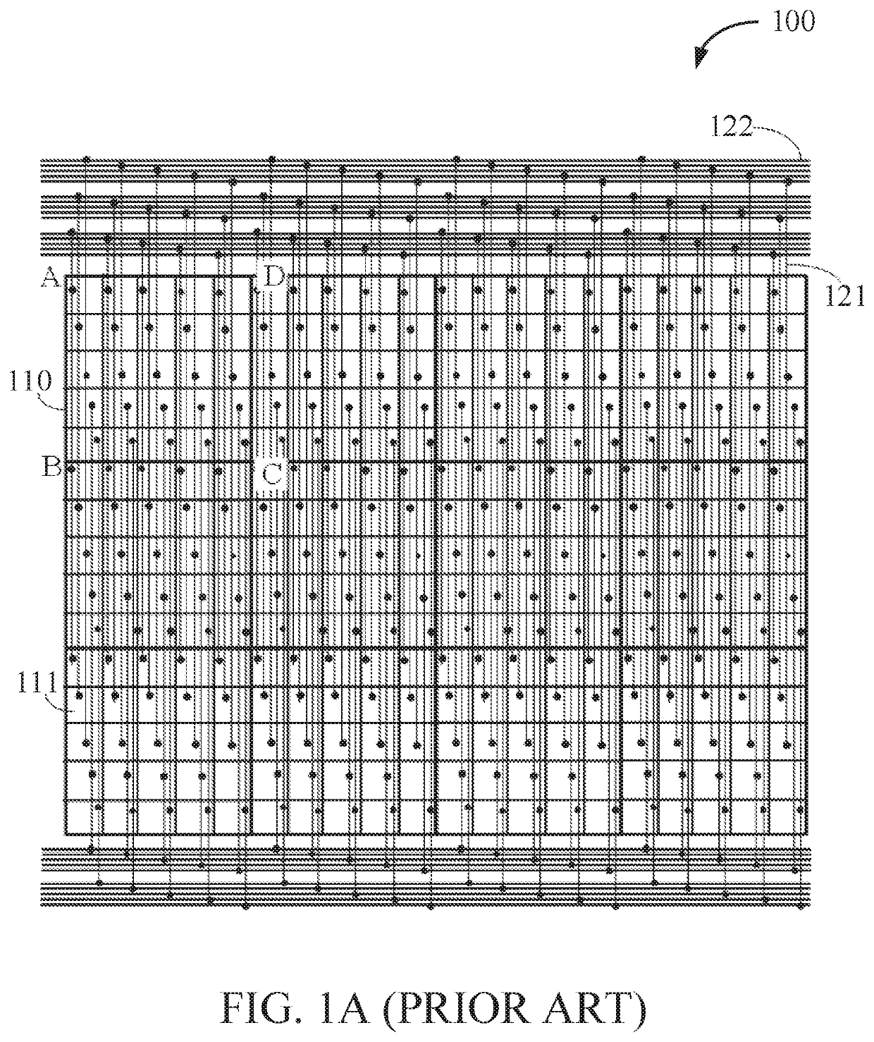
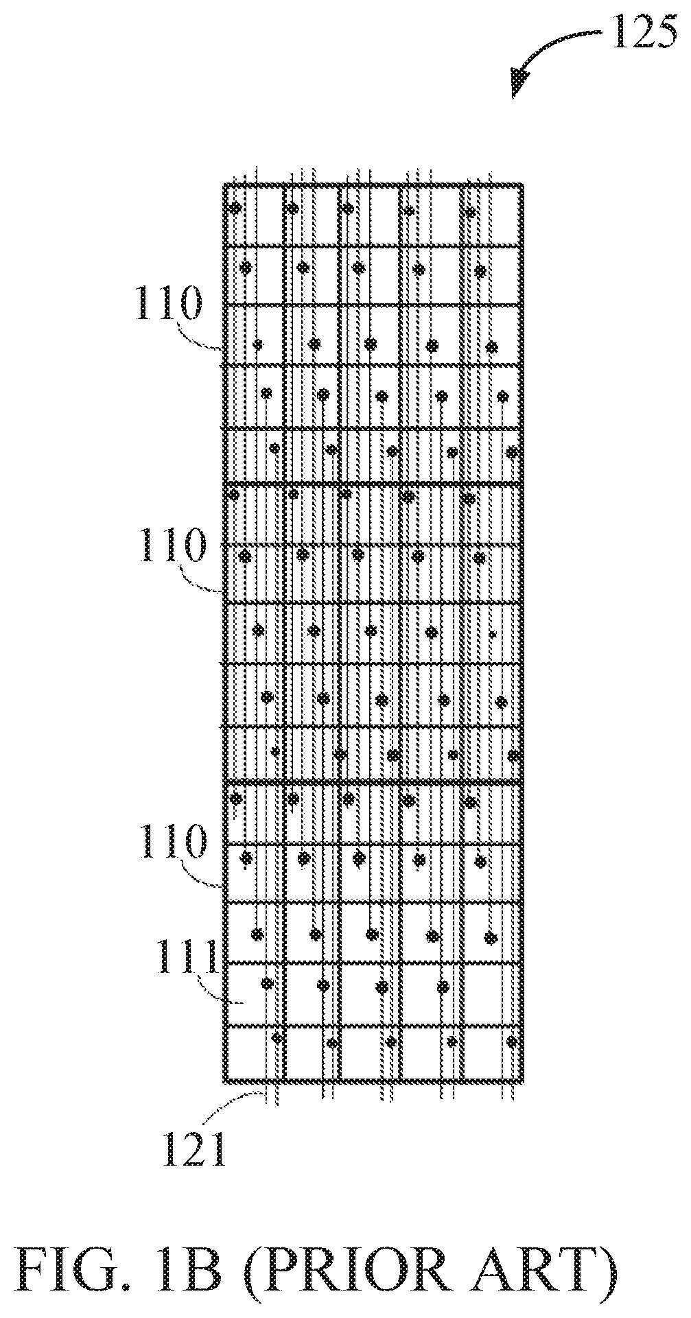
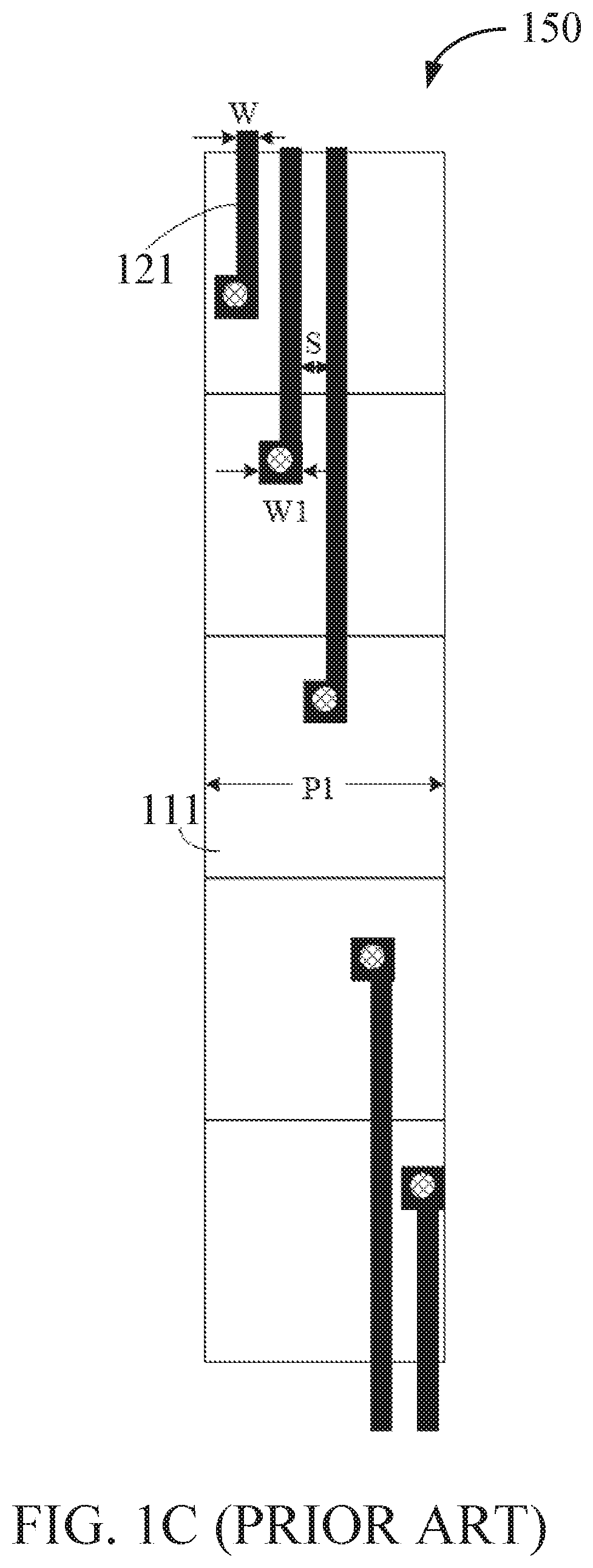
[0026]FIG. 1A depicts a schematic diagram 100 of wiring in a conventional light field display device, FIG. 1B depicts a schematic diagram 125 of wiring in three light-emitting units in a column of the conventional light field display device of FIG. 1A, and FIG. 1C depicts a schematic diagram 150 of wiring of a column of light-emitting points in a light-emi...


PUM


Abstract

An array substrate is provided, including a substrate, wherein the substrate is provided with a plurality of electrodes and a plurality of first signal lines, each of the electrodes being correspondingly connected with a first signal line. In some examples, the first signal lines extend in the same direction. In some examples, at least two of the plurality of first signal lines are located in different layers of an insulating spacer from each other. In some examples, orthographic projections on the substrate of at least two of the first signal lines in the different layers at least partially overlap. Accordingly, a light field display device comprising the array substrate is also provided. The array substrate can reduce a light-emitting point size and increase a density distribution of light-emitting points.

Description

FIELD[0001]The present description relates generally to the field of display technologies, and embodiments of an array substrate and a light field display device.BACKGROUND AND SUMMARY[0002]In recent years, light field display has become a burgeoning field of research. For example, light field display features prominently in the development of next-generation 3D display devices. In a conventional light field display device, a light-driven display unit utilizes a two-dimensional matrix, or array, composed of a plurality of light-emitting points, such as a pixel or a sub-pixel. A driving structure provides a driving signal for an electrode of the light-emitting point via a signal line, whereby the light-emitting point projects a beam of light according to the driving signal into space.[0003]In order to improve a perceived display effect, the light field display device needs to be provided with a large number of light-emitting points. However, in current light field display devices, ea...

Claims


Application Information

Patent Timeline
IPC IPC(8): H01L27/32H04N13/302
CPCH01L27/3276H01L2227/323H04N13/302G09G3/3208H10K59/179H10K59/131G09G3/32G09G2300/0426G09G3/003H10K59/1201
Inventor YANG, MINGZHANG, CANXUAN, MINGHUACHEN, LIANGCHEN, XIAOCHUANZHAO, WENQING
Owner BOE TECH GRP CO LTD
Why Eureka
Try Eureka