

System and method for harvesting fruit
- Summary
- Abstract
- Description
- Claims
- Application Information
AI Technical Summary
Benefits of technology
Problems solved by technology
Method used
Image

Examples
Embodiment Construction
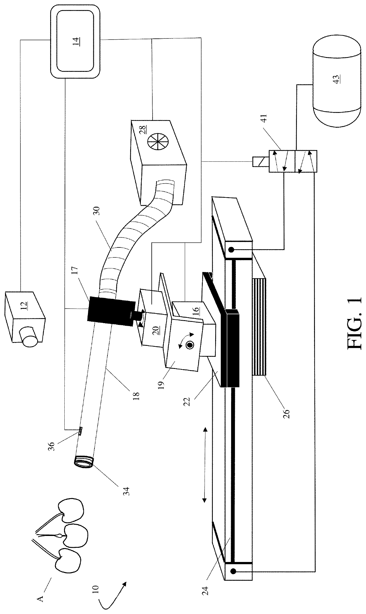
[0026]As generally shown in FIG. 1, the method and apparatus described herein comprises a robotic apple harvesting system 10. The system 10 includes a three-dimensional stereo vision camera 12 mounted in an elevated position and directed to an area of the tree canopy that includes one or more apples A designated for harvest. The camera 12 is in electronic communication with a processor / controller 14 which processes the camera 12 images and communicates control instructions to other elements of the harvest system 10.
[0027]Specifically, as schematically shown in FIG. 1, the controller 14 communicates with a tilting mechanism 16 which moves / tilts a relatively small diameter selection and detachment tube 18 in a vertical plane. Similarly, a panning mechanism 20 moves the selection tube 18 in a horizontal plane. A selection tube control assembly 17 mechanically manipulates the selection tube 18. The selection tube control assembly 17 comprises a mechanical linkage between the tilt 16 and...
PUM
 Abstract
Description
Claims
Application Information