Work Vehicle

Pending Publication Date: 2021-09-02
KUBOTA LTD
View PDF5 Cites 0 Cited by
  • Summary
  • Abstract
  • Description
  • Claims
  • Application Information

AI Technical Summary

Benefits of technology

The patent text describes a system that helps to quickly warm up an engine in a vehicle that has a long cooling water passage. The system is controlled by a thermostat that prevents cooling water from being introduced into the engine when the water is too cold. This allows the cooling water to be introduced from a bypass passage, which is typically a lower temperature than the engine, helping to speed up the warmup process.

Problems solved by technology

With the above-described work vehicle, even when the temperature of the cooling water is low, since the cooling water from the engine which has passed through a leak hole of the thermostat passes and circulates through the radiator, an engine warm-up operation takes long time.
Further, if the leak hole of the thermostat were omitted in order to shorten the time for engine warmup, hunting of temperature of the cooling water would occur.

Method used


Image

  • Work Vehicle
  • Work Vehicle
  • Work Vehicle

Examples


Embodiment Construction

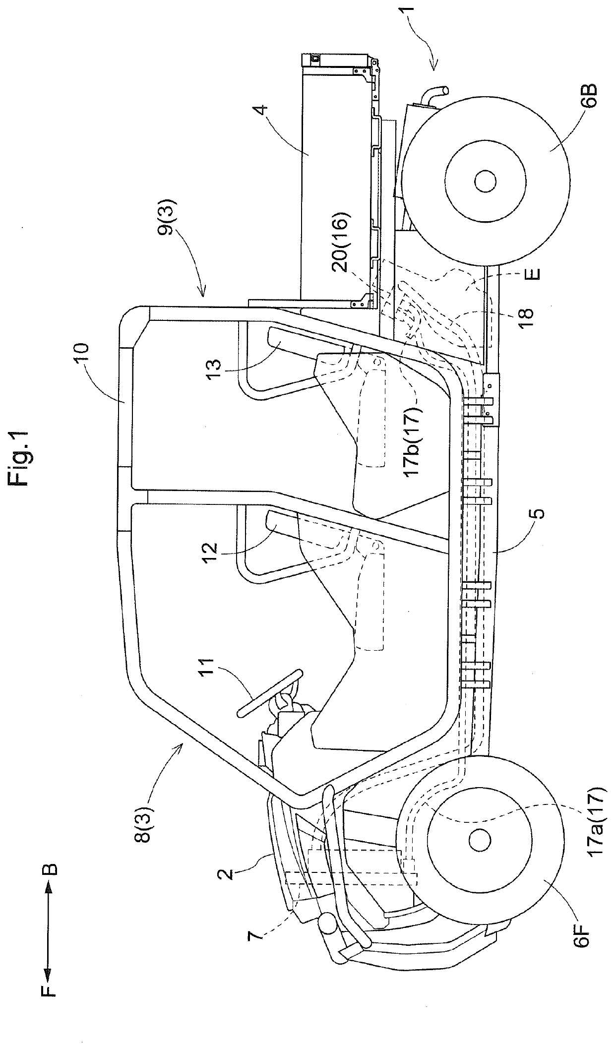
[0037]Next, an embodiment of the present invention will be explained with reference to the accompanying drawings. In the following explanation, in FIG. 1, a direction of arrow F is defined as “vehicle body front side”, a direction of arrow B is defined as “vehicle body rear side”, a direction on the left side facing the direction of arrow F is defined as “vehicle body left side” and a direction on the right side facing the direction of arrow F is defined as “vehicle body right side”, respectively.

Generation Arrangement of Multiple-Purpose Vehicle

[0038]FIG. 1 shows a utility vehicle (a multiple-purpose vehicle) corresponding to what is referred to as a “work vehicle” relating to the present invention. This vehicle includes a traveling vehicle body 1, an engine hood 2, a riding section 3 where passengers will ride, a dumping type load carrying bed 4, and a water-cooled engine E. The traveling vehicle body 1 includes a vehicle body frame 5, left and right front wheels 6F and left and r...


PUM


Abstract

A thermostat is provided at a connection portion between a cooling water supply passage and a bypass passage. When the temperature of the cooling water lies in a low temperature range lower than a first reference temperature, the thermostat allows introduction of the cooling water from the cooling water discharge passage into the cooling water supply passage via the bypass passage and also prevents introduction of the cooling water from the radiator into the engine via the cooling water supply passage. When the temperature of the cooling water lies in a high temperature range equal to or higher than a second reference temperature which is higher than the first reference temperature, the thermostat allows introduction of the cooling water from the radiator into the engine via the cooling water supply passage and also prevents introduction of the cooling water from the cooling water discharge passage into the cooling water supply passage via the bypass passage.

Description

CROSS-REFERENCE TO RELATED APPLICATION[0001]This application claims priority to Japanese Patent Application No. 2020-033521 filed Feb. 28, 2020, the disclosure of which is hereby incorporated by reference in its entirety.BACKGROUND OF THE INVENTION1. Field of the Invention[0002]The present invention relates to a work vehicle.2. Description of Related Art[0003]Conventionally, as a work vehicle, there is known a work vehicle described in e.g. JP2018-204498A. The work vehicle described in Patent Document 1 includes a water-cooled engine (referred to as an “engine (14)” in the document), a radiator for cooling water for cooling the engine (referred to as “radiator (8)” in the document), and a thermostat.[0004]With the above-described work vehicle, even when the temperature of the cooling water is low, since the cooling water from the engine which has passed through a leak hole of the thermostat passes and circulates through the radiator, an engine warm-up operation takes long time. Furt...

Claims


Application Information

Patent Timeline
IPC IPC(8): F01P7/16F01P3/20
CPCF01P7/161F01P2050/22F01P2025/36F01P3/20F01P7/16
Inventor TANAKA, KAZUHIRO
Owner KUBOTA LTD
Why Eureka
Try Eureka