Device And Method For Venting A Crank Casing Of An Internal Combustion Engine

Active Publication Date: 2019-01-31
MAN NUTZFAHRZEUGE AG +1
View PDF0 Cites 2 Cited by
  • Summary
  • Abstract
  • Description
  • Claims
  • Application Information

AI Technical Summary

Benefits of technology

The invention aims to provide a device and method for ventilating the crankcase of an internal combustion engine in a vehicle, particularly a utility vehicle. The device ensures reliable functioning while preventing the introduction of oil into the engine's intake tract.

Problems solved by technology

In the case of such a ventilation arrangement, however, problems arise if a ventilation line dips with its gas inlet opening into the oil sump oil and then a large quantity of oil sump oil is conveyed via the ventilation line into the intake tract of the internal combustion engine.
In the worst case, this can lead to severe engine damage.

Method used


Image

  • Device And Method For Venting A Crank Casing Of An Internal Combustion Engine
  • Device And Method For Venting A Crank Casing Of An Internal Combustion Engine
  • Device And Method For Venting A Crank Casing Of An Internal Combustion Engine

Examples


first embodiment

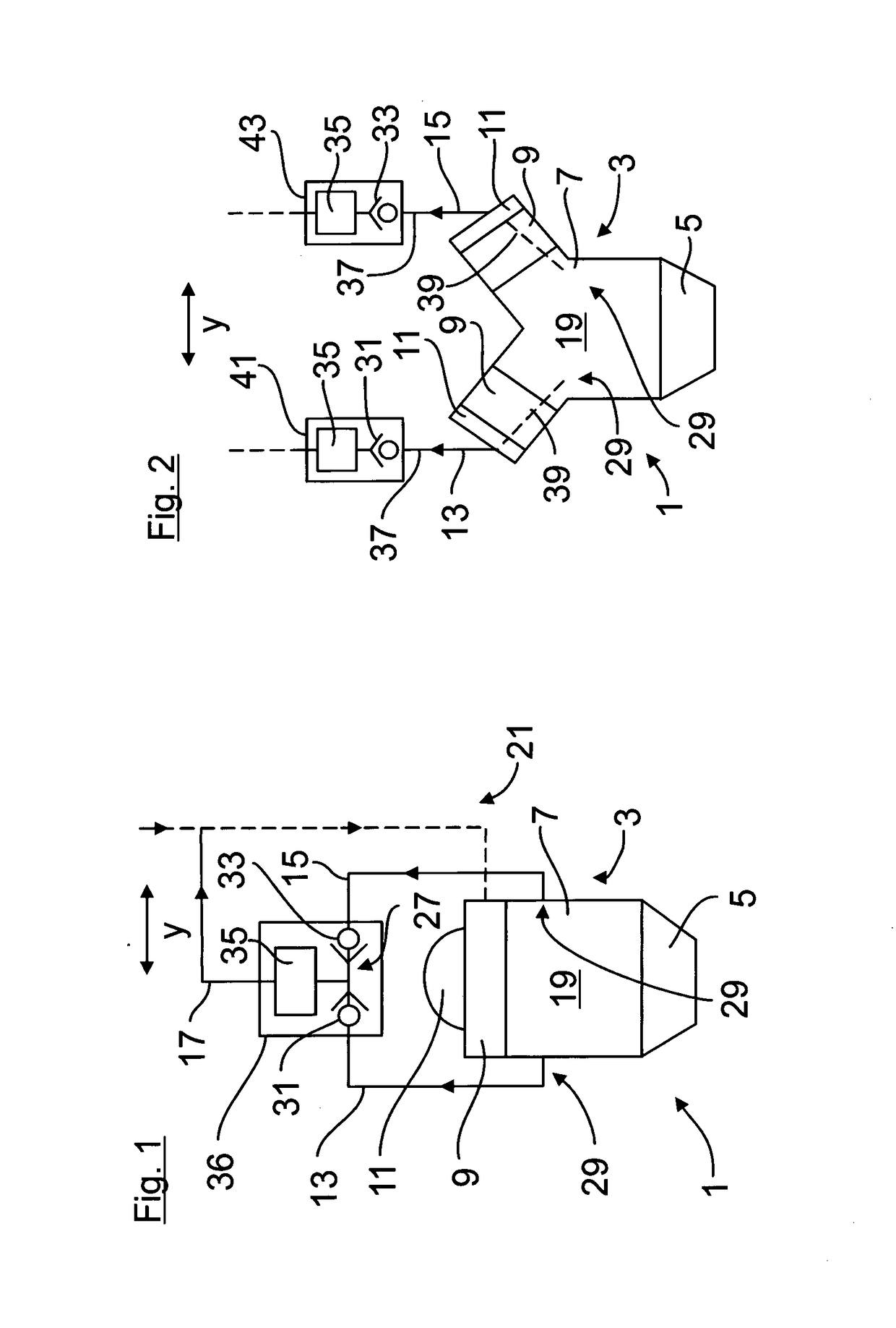
[0040]FIG. 1 shows an apparatus 1 according to the invention. The apparatus 1 has an internal combustion engine 3, which is designed in this case for example as an in-line engine, and which comprises an oil sump 5, a crankcase 7, a cylinder head 9 and a cylinder head cover 11. The apparatus 1 furthermore has multiple, in this case for example three, ventilation channels or ventilation lines 13, 15, 17, by which gases flowing into a crank chamber 19 of the crankcase 7, in particular blow-by gases, can be conducted into an intake tract 21, indicated by dashed lines, of the internal combustion engine 3. As an alternative to the introduction into the intake tract 21, it is also possible for the gases flowing into the crank chamber 19 to be conducted directly into the atmosphere or into the surroundings of the internal combustion engine 3, if the gases, before being introduced into the atmosphere, are also purified or cleaned by a suitable cleaning device.

[0041]The ventilation channels 1...

seventh embodiment

[0051]FIG. 7 shows the apparatus 1. The internal combustion engine 3 is formed in this case as a four-cylinder in-line engine. The apparatus 1 has in this case multiple, in this case for example four, ventilation channels 67, which each have a channel section 69 arranged outside the internal combustion engine 3 and a channel section 71 running through the internal combustion engine 3. The channel section 69 is formed here by a pipeline that opens out at the cylinder head cover 11. Here, the channel section 71 runs through the cylinder head cover 11 and through the cylinder head 9 to the crank chamber 19.

[0052]Furthermore, gas inlet openings 73 of the ventilation channels 67 are in this case arranged so as to be distributed uniformly over the crank chamber 19 in an internal combustion engine longitudinal direction x. It is achieved in this way that, in any inclination of the internal combustion engine 3 about a transverse axis formed by the internal combustion engine transverse direc...

second embodiment

[0061]FIGS. 13 and 14 show the shut-off valve 31. The shut-off valve 31 is formed in this case by a float valve arranged in a labyrinthine, U-shaped section 93 of the ventilation channel 13. The U-shaped section 93 has, as viewed in a fluid flow direction, a first U limb 95, a U base 97 and a second U limb 99. The shut-off valve 31 is in this case arranged for example in the second U limb 99 of the U-shaped section 93.

[0062]The shut-off valve 31 has in this case a float body 101 formed as a sealing element and which is pressed against a corresponding sealing seat 103 in order to shut off the fluid flow through the ventilation channel 13 and which opens up a defined flow cross section in order to enable the fluid flow through the ventilation channel 13. Here, FIG. 13 shows the float body 101 in its closed position, in which it shuts off the fluid flow through the ventilation channel 13. FIG. 14 shows the float body in its open position, in which the float body 101 enables the fluid f...


PUM


Abstract

The invention relates to a device for venting a crank casing of an internal combustion engine for a vehicle, having a plurality of venting ducts (13, 15, 53, 67, 84) by means of which gases flowing into a crank casing space (19) of the crank casing (7) can be conducted out of the crank casing space (19) again, wherein gas inlet openings (29, 55, 73), opening into the crank casing space (19), of the venting ducts are arranged in such a way that in a first defined inclination position of the internal combustion engine (3) a first venting duct does not dip with its gas inlet opening (29) into oil trough oil which is collected in an oil trough (5) of the internal combustion engine (3), and a second venting duct dips with its gas inlet opening (29, 55, 73) into the oil trough oil, wherein in a second defined inclination position of the internal combustion engine (3) which differs from the first inclination position the first venting duct (13, 67) dips with its gas inlet opening (29) into the oil trough oil and the second venting duct does not dip with its gas inlet opening (29, 55, 73) into the oil trough oil. According to the invention, a control device is provided by means of which a flow of fluid through the venting ducts can be shut off and released fluidically as a function of the inclination of the internal combustion engine (3), wherein in the first inclination position of the internal combustion engine (3) the control device releases the first venting duct and shuts off the second venting duct, and wherein in the second inclination position of the internal combustion engine (3) the control device releases the second venting duct and shuts off the first venting duct.

Description

CROSS-REFERENCE TO RELATED APPLICATIONS[0001]This is a U.S. national stage of application No. PCT / EP2017 / 000048 filed 18 Jan. 2017. Priority is claimed on European Application No. 10 2016 000 632.3 filed 25 Jan. 2016, the content of which is incorporated herein by reference in its entirety.BACKGROUND OF THE INVENTION1. Field of the Invention[0002]The invention relates to an apparatus for ventilating a crankcase of an internal combustion engine, to a method for ventilating a crankcase of an internal combustion engine, and to a vehicle, in particular utility vehicle, having the apparatus and / or for carrying out the method.2. Description of the Related Art[0003]It is known to provide, on an internal combustion engine, a crankcase ventilation device by which gases that flow into a crank chamber of the internal combustion engine during the operation of the internal combustion engine, in particular blow-by gases, are conducted out of the crank chamber again and introduced into an intake t...

Claims


Application Information

Patent Timeline
IPC IPC(8): F01M13/00F01M13/04
CPCF01M13/0011F01M13/04F01M2013/0044F01M11/065
Inventor SPRICKMANN KERKERINCK, STEFANHERDERING, HEINZ
Owner MAN NUTZFAHRZEUGE AG
Why Eureka
Try Eureka