
Guidewire Connector and Ultrasonic Imaging Apparatus

Active Publication Date: 2021-01-21
FUJIFILM HEALTHCARE CORP
View PDF0 Cites 0 Cited by
  • Summary
  • Abstract
  • Description
  • Claims
  • Application Information

AI Technical Summary

Benefits of technology

The technical effect of this patent is to provide a guidewire connector that allows for the efficient and safe connection of a guidewire with a photo-acoustic ultrasonic wave generator while maintaining the cleanliness of the guidewire. Inhibition of introduction of another instrument can be prevented, and the guidewire can be easily detached for disposal.

Problems solved by technology

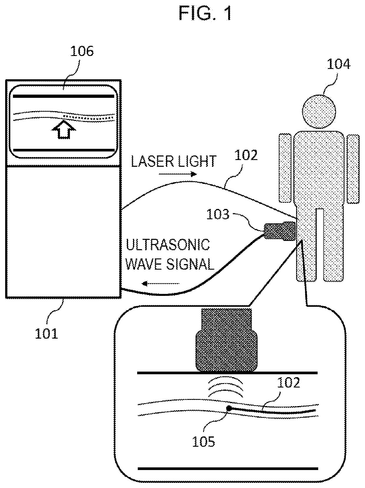
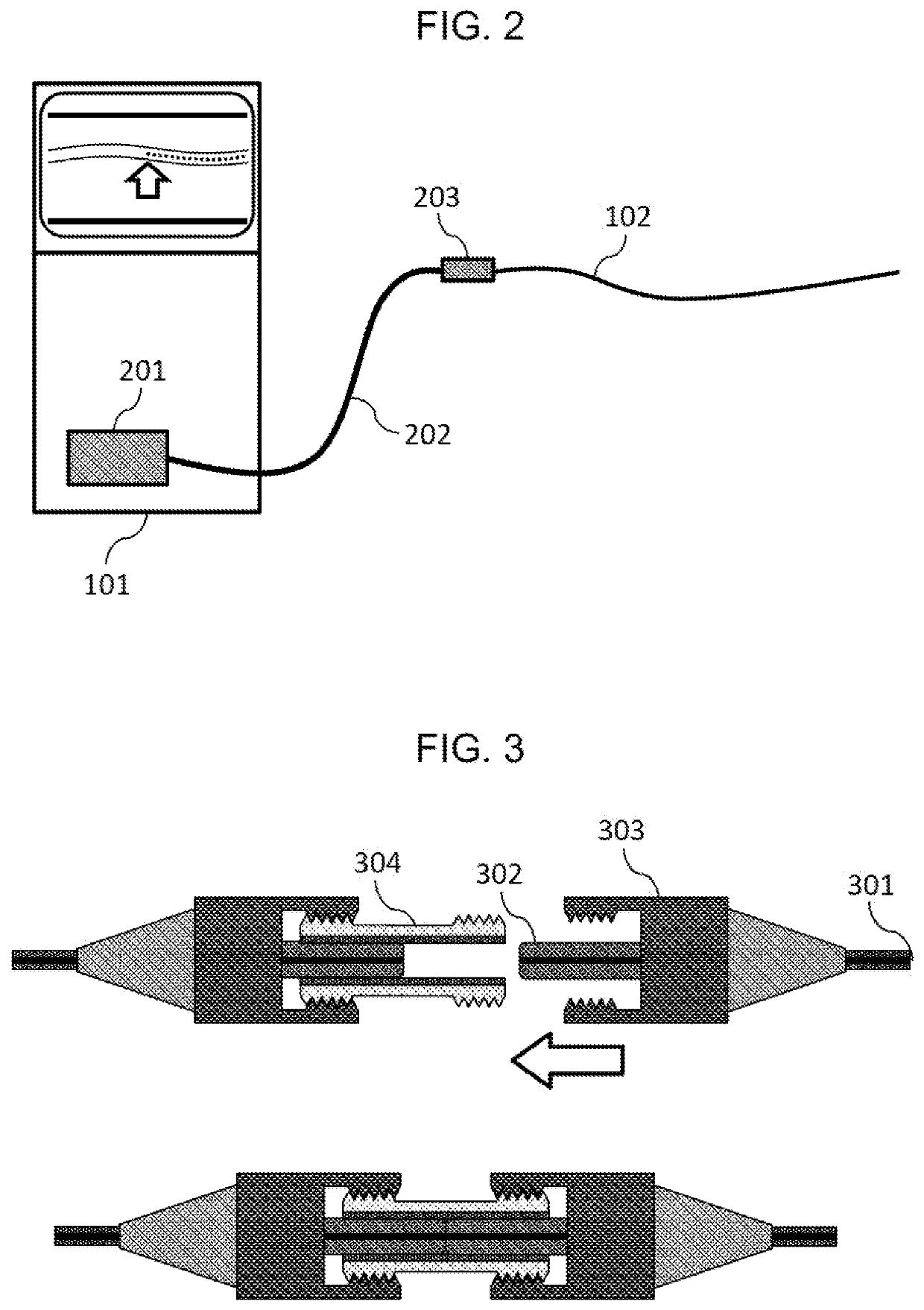
On the other hand, the ultrasonic imaging apparatus 101 and a laser body are not necessarily clean since they are used for many times. Therefore, when using a general optical fiber connector, when the guidewire is connected to the laser body, the distal end portion of the guidewire may become unclean.
The cleanliness of another treatment instrument may also be impaired by the distal end portion of the guidewire whose cleanliness is impaired since another instrument is inserted from the distal end of guidewire.
However, the technique of PTL 2 keeps cleanliness by providing a sterile barrier, and does not describe a requirement relating to an outer diameter of the optical fiber connector or a method for meeting the requirement.
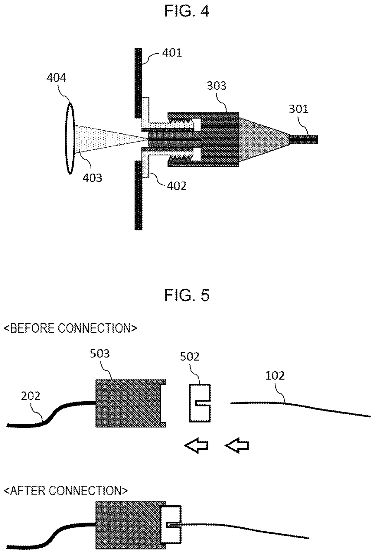
However, the connection unit 503 is not disposable, and cleanliness is not ensured.

Method used


Image

  • Guidewire Connector and Ultrasonic Imaging Apparatus
  • Guidewire Connector and Ultrasonic Imaging Apparatus
  • Guidewire Connector and Ultrasonic Imaging Apparatus

Examples


first embodiment

[0052]The guidewire connector according to the first embodiment includes the adapter unit 502 detachable to the ultrasonic imaging apparatus 101, and fixes the guidewire 102 to the adapter unit 502. Accordingly, the cleanliness of the guidewire 102 can be kept since the adapter unit 502 and the guidewire 102 can be used as disposable members.

[0053]In the guidewire connector according to the first embodiment, the outer diameter of the clasp 605 is smaller than the outer diameter of the guidewire 102. Therefore, the clasp 605 does not inhibit an introduction of another instrument when the other instrument such as catheter is introduced along the guidewire 102. Accordingly, the guidewire 102 can be fixed without inhibiting the introduction of the other instrument.

second embodiment

[0054]FIG. 12 is a cross-sectional side view showing a structure of a guidewire connector according to the second embodiment. The adapter unit 502 in the second embodiment has a cable-shaped structure whose entire length is extended by the optical fiber 1204. The adapter unit 502 in the second embodiment includes a connection unit 1201, an optical fiber 1204, and an optical fiber connector 1203. One end of the connection unit 1201 is connected to the guidewire 102. The other end of the connection unit 1201 is connected to the optical fiber 1204. The adapter unit 502 and the ultrasonic imaging apparatus 101 are connected by fitting the optical fiber connector 1203 to a similar optical fiber connector provided in the ultrasonic imaging apparatus 101.

[0055]Although the laser light is converged at the end of the adapter unit 502 in the first embodiment, the laser light is introduced to the connection unit 1201 by the optical fiber 1204 in the second embodiment. Similar as in the first e...


PUM


Abstract

Provided is a guidewire connector that does not interfere with an introduction of another in-body insertion instrument and is capable of maintaining cleanliness of the guidewire when connecting a guidewire mounted with a photo-acoustic ultrasonic wave generator. The guidewire connector according to the present disclosure includes an adapter member detachably attached to an light emitting apparatus, and a wire fixing member attaching the guidewire to the adapter member, in which the wire fixing member has an outer diameter equal to or smaller than an outer diameter of the guidewire.

Description

CROSS-REFERENCE TO RELATED APPLICATION[0001]This application claims the priority of Japanese Patent Application No. 2019-132535 filed Jul. 18, 2019, which is incorporated herein by reference in its entirety.BACKGROUND OF THE INVENTION1. Field of the Invention[0002]The present disclosure relates to a connector for a guidewire housing an optical waveguide therein.2. Description of the Related Art[0003]There is a treatment method for performing treatment in a body in a minimally invasive manner using a small-diameter treatment instrument such as a catheter. In such treatment, although the treatment instrument is put into the body by inserting a needle or the like into a body surface such that burden on a patient is smaller than that in laparotomy and thoracotomy surgeries, it is necessary to obtain an image of a treatment site with a device for imaging an inside of the body since the treatment instrument cannot be seen directly. As an example of such minimally invasive treatment, there...

Claims


Application Information

Patent Timeline
IPC IPC(8): A61B5/00G02B6/42G02B6/38
CPCA61B5/0095G02B6/3825G02B6/4204A61B2562/228A61B5/06A61B8/0841G02B6/0006G02B6/4292G02B6/3897
Inventor IMAI, RYOTANAKA, TOMOHIKO
Owner FUJIFILM HEALTHCARE CORP
Learn More