
Jig for connector plug, connector plug and cable with connector plug

a technology of connector plugs and connector plugs, which is applied in the direction of electrical equipment, coupling device connections, instruments, etc., can solve the problems of difficult design of connector plugs, damage to difficulty in increasing the thickness of the upper surface portion of the locking portion of the slider, so as to ensure the strength and avoid the damage of the locking portion. , the effect of easy attachment and removal of the connector plugs

Active Publication Date: 2021-09-09
SEIKOH GIKEN
View PDF0 Cites 4 Cited by
  • Summary
  • Abstract
  • Description
  • Claims
  • Application Information

AI Technical Summary

Benefits of technology

The present invention provides a jig for inserting and detaching a connector plug from an adapter, even in dense configurations. The jig has an insertion portion that can be inserted into a slot on the slider of the connector plug, and an operation portion extended in the detaching direction. The insertion portion has two locking portions that can be locked to the inner wall of the slot, and the state of the locking can be released by applying force to the operation portion. The connector plug has the jig attached, making it easier to handle and preventing damage to the locking portion. The strength of the connector plug is increased, making it more durable and resistant to damage.

Problems solved by technology

Thus, it is difficult to increase the thickness of the upper surface portion of the locking portion of the slider.
Accordingly, it is difficult to design the connector plug so as to ensure sufficient strength even when the external force exceeding the assumed pull-out force is applied.
As a result, when the jig is pulled in the detaching direction by the force stronger than the assumed force in a state that the slider and the jig are in parallel (horizontal) with each other, the locking portion may be damaged.
Accordingly, when the jig is inclined upward exceeding the assumed inclination angle, the locking portion may be damaged.

Method used


Image

  • Jig for connector plug, connector plug and cable with connector plug
  • Jig for connector plug, connector plug and cable with connector plug
  • Jig for connector plug, connector plug and cable with connector plug

Examples


Embodiment Construction

[0031]Hereafter, embodiments of the present invention will be explained with reference to the drawings shown as an example.

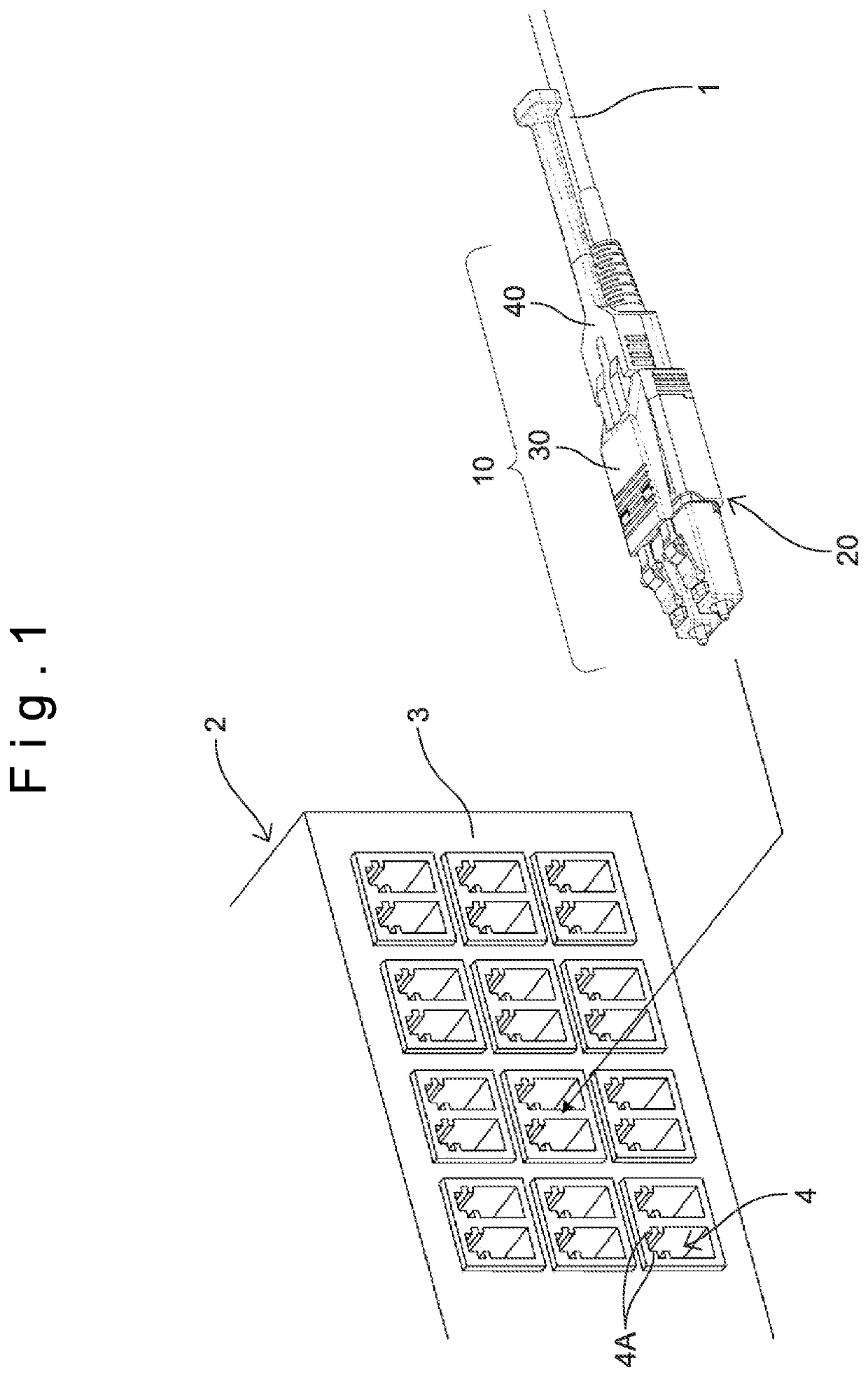
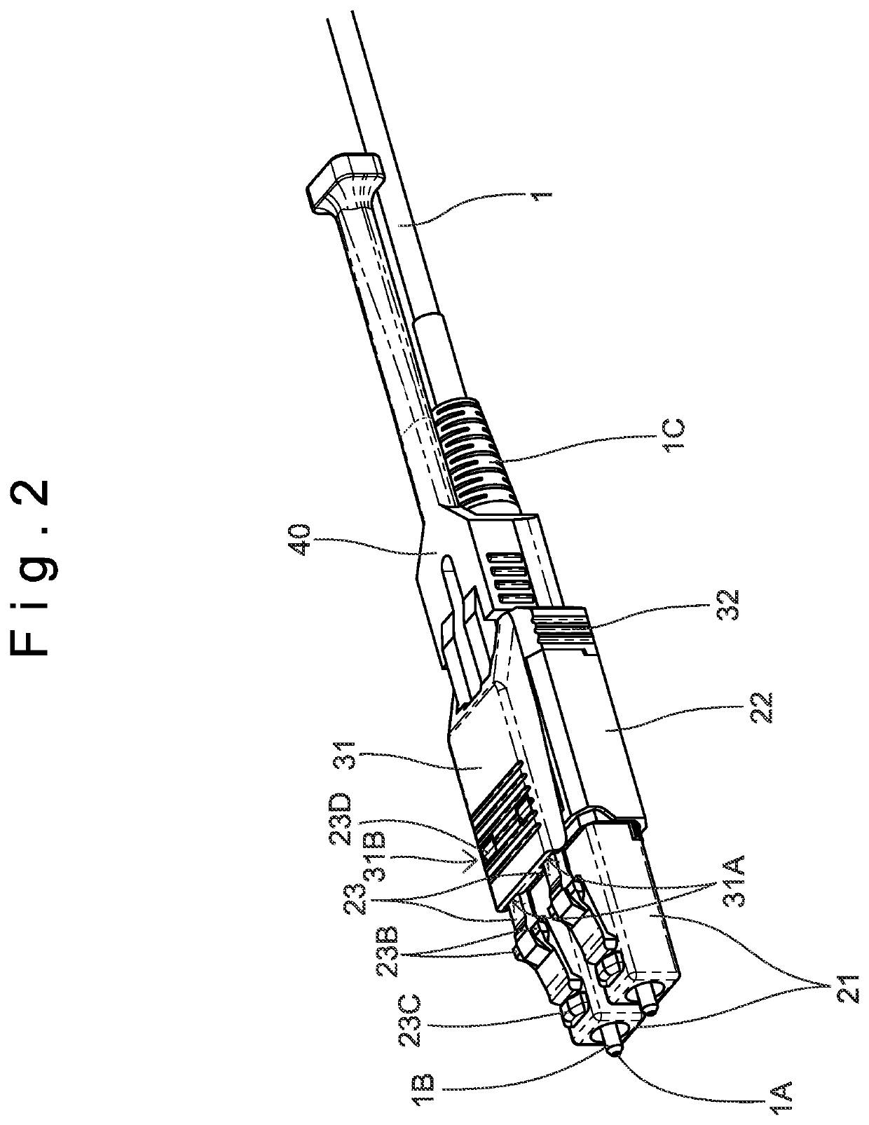
[0032]FIG. 1 is a perspective view for explaining an outline of a connector plug 10. As shown in FIG. 1, the connector plug 10 is attached to the end portion of an optical fiber cable 1. The connector plug 10 attached to the optical fiber cable 1 is fitted to an adapter 4 (into a fitting hole) provided on a panel 3 of a device 2. Consequently, the optical fiber cable 1 is connected with the optical module or another optical fiber cable via the connector plug 10 and the adapter 4. In the following explanation, the direction of detaching (removing) the connector plug 10 from the adapter 4 is referred to as a detaching direction (removing direction), and the direction of inserting (attaching) the connector plug 10 to the adapter 4 is referred to as an inserting direction (attaching direction), where the inserting direction is an opposite direction of the detaching ...


PUM


Abstract

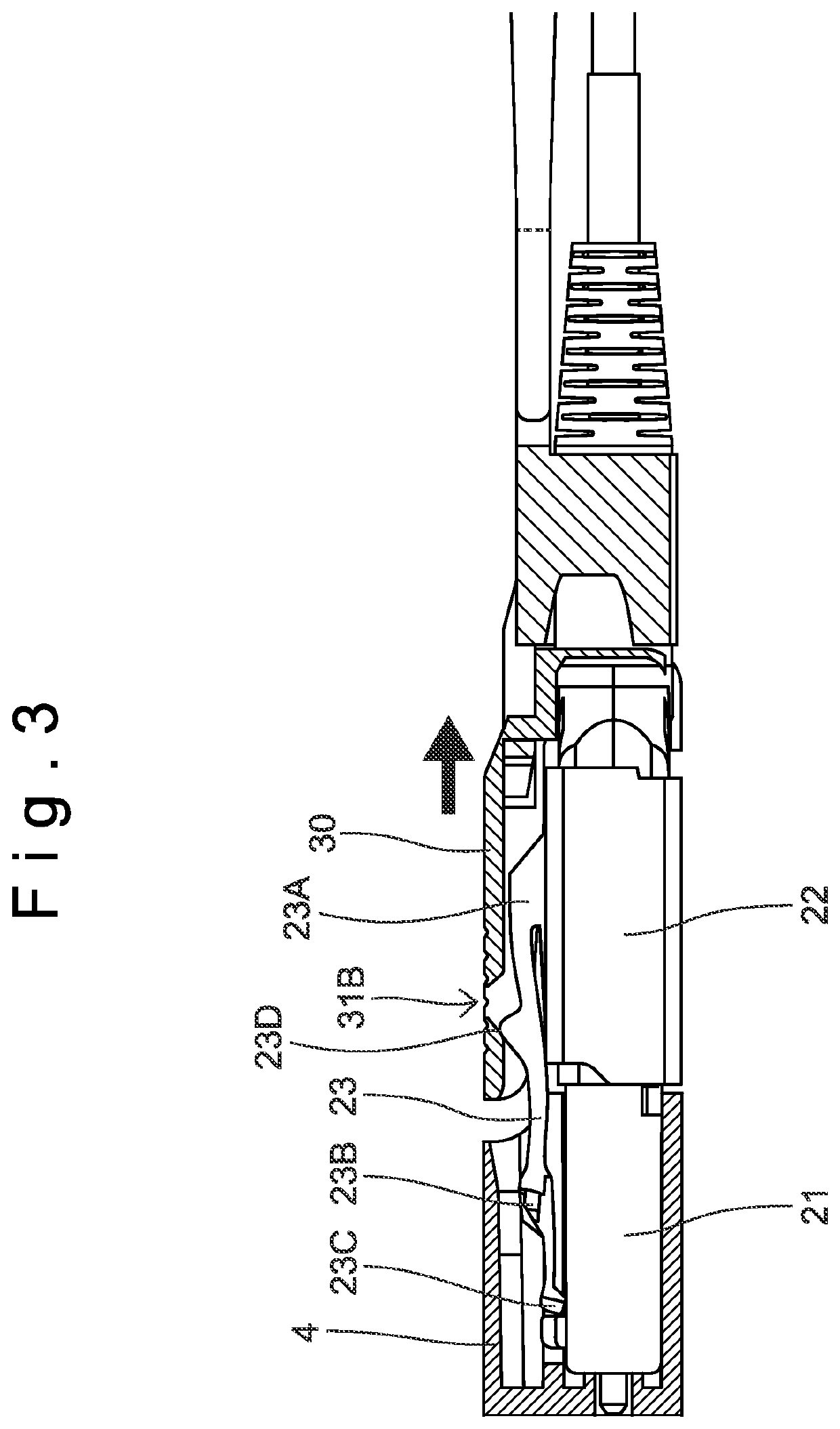
A connector plug has a connector plug body, a slider supported on the connector plug body and a jig attachable to the slider. The jig has an insertion portion which can be inserted into a slot of the slider and an operation portion extended from the insertion portion. The insertion portion has first and second insertion portions separated from each other by a predetermined distance. The slider can be moved in the detaching direction when the jig is moved in the detaching direction in a state that a first locking portion of the first insertion portion and a second locking portion of the second insertion portion are locked to the inner wall of the slot, and the locked state of the first locking portion and the second locking portion can be released when a force is applied to the operation portion in an inside direction to shorten the predetermined distance.

Description

CROSS-REFERENCES TO RELATED APPLICATIONS[0001]This patent specification claims priority to U. S. Provisional Application Ser. No. 62 / 985,871, filed Mar. 5, 2020 and Japanese patent application, No. 2020-064307 filed on Mar. 30, 2020 in the Japan Patent Office, the entire contents of which are incorporated by reference herein.BACKGROUND OF THE INVENTION1. Field of the Invention[0002]The present invention relates to a jig for connector plug, a connector plug and a cable with connector plug.2. Description of Related Art[0003]An optical fiber cable is connected with optical modules such as a receiver and a transmitter or another optical fiber cable via an adapter (including a so-called receptacle). Accordingly, a connector plug to be fitted to the adapter is provided on the end portion of the optical fiber cable. In the communication devices on which the optical modules are mounted and the devices such as a fiber distribution frame for relaying the optical fiber cables with each other, ...

Claims


Application Information

Patent Timeline
Patent Type & Authority Applications(United States)
IPC IPC(8): H01R13/506H01R13/625
CPCH01R13/506H01R13/625G02B6/3825G02B6/3893G02B6/3897G02B6/3898G02B6/3879
Inventor TAIRA, JUNJITAKASHI, SHUICHISHIOKAWA, NAOTOSHIJIBIKI, MASAYUKI
Owner SEIKOH GIKEN
Learn More