Protective recreational sports helmet with components additively manufactured to manage impact forces

a technology for recreational sports and helmets, applied in the field of protective sports helmets, can solve the problems of not using advanced techniques in the creation of helmets, and most traditional helmets do not contain components

Pending Publication Date: 2021-09-16
RIDDELL
View PDF0 Cites 3 Cited by
  • Summary
  • Abstract
  • Description
  • Claims
  • Application Information

AI Technical Summary

Benefits of technology

[0010]To efficiently create members of the energy attenuation assembly having differing structural makeups and / or chemical compositions, the development process involves the usage of advanced structures (e.g., lattice cell types), advanced materials with tailored chemical compositions (e.g., specific light sensitive polymers), and advanced helmet design / manufacturing techniques (e.g., finite element analysis, neural networks, additive manufacturing) are utilized while accounting for the player's specific playing level, position, medical history and / or to at least one of the player's anatomical features. The energy attenuation assembly is positioned within an outer shell of the protective contact sports helmet or the protective recreational sports helmet. When the contact sports helmet is configured for use while playing American football, hockey or lacrosse, the helmet includes a face guard or facemask and a chin strap.

Problems solved by technology

However, most traditional helmets do not use advanced techniques to create a helmet that is specifically designed to respond in a certain manner when an impact or series of impacts are received by the helmet.
Additionally, most traditional helmets do not contain components that are specifically selected or tailored to a particular player's playing level, position, medical history and / or to at least one of the player's anatomical features.

Method used


Image

  • Protective recreational sports helmet with components additively manufactured to manage impact forces
  • Protective recreational sports helmet with components additively manufactured to manage impact forces
  • Protective recreational sports helmet with components additively manufactured to manage impact forces

Examples


first embodiment

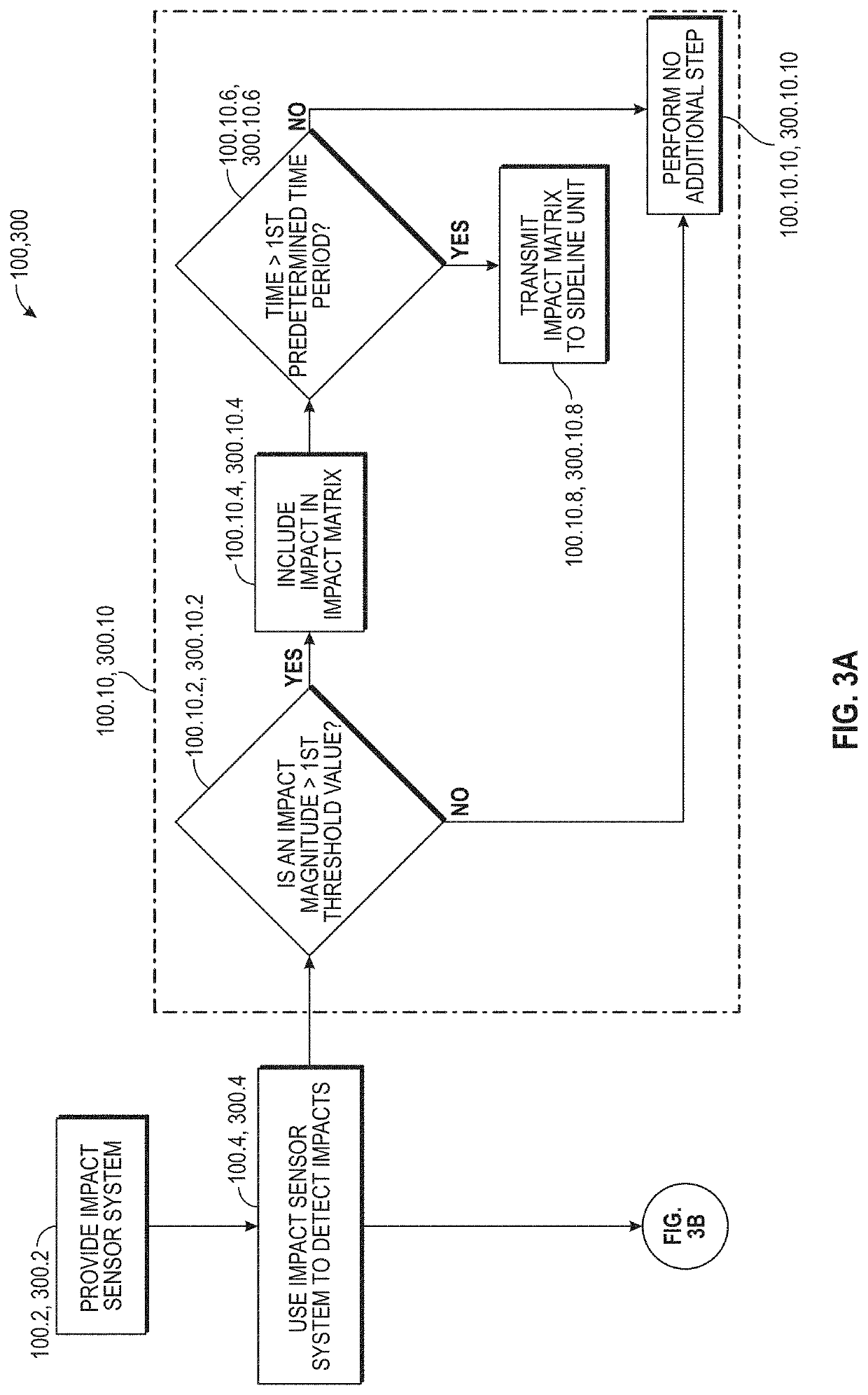
[0136]While the IHU 100.2.4, 300.2.4 is performing the HIE algorithm 100.10, 300.10, the IHU 100.2.4, 300.2.4 is also performing the alert algorithm 100.50, 300.50 shown in FIG. 3B. Referring to FIG. 3B, the microcontroller 100.2.4.12, 300.2.4.12 will calculate an impact value in step 100.50.2, 300.50.2. In one embodiment, this is done by first determining the linear acceleration, rotational acceleration, head injury criterion (HIC), and the Gadd severity index (GSI) for the given impact. The algorithms used to calculate these values are described in Crisco J J, et al. An Algorithm for Estimating Acceleration Magnitude and Impact Location Using Multiple Nonorthogonal Single-Axis Accelerometers. J BioMech Eng. 2004; 126(1), Duma S M, et al. Analysis of Real-time Head Accelerations in Collegiate Football Players. Clin J Sport Med. 2005; 15(1):3-8, Brolinson, P. G., et al. Analysis of Linear Head Accelerations from Collegiate Football Impacts. Current Sports Medicine Reports, vol. 5, n...

second embodiment

[0273]Below are a number of exemplary embodiments of the front energy attenuation member model that may be created in step 190.8, 290.8, 390.8. In the first exemplary embodiment, the chemical composition and the structural makeup of the front energy attenuation member 2010, 3010 may be consistent throughout the model. Specifically, the front energy attenuation member model may be comprised of: (i) a consistent blend of two types of polyurethane and (ii) a single lattice cell type. In a second embodiment, the chemical composition of the front energy attenuation member model may be consistent throughout the entire model, while the structural makeup may vary between member regions. Specifically, the model may have: (i) a consistent blend of two types of polyurethane, (ii) a first region, which has a first lattice cell type and a first density, and (iii) second region, which has a first lattice cell type and a second density. In this example, the second lattice density may be greater or...

third embodiment

[0274]In a third embodiment, the chemical composition of the front energy attenuation member model may be consistent throughout the model, while the structural makeup changes in various regions of the model. Specifically, the front energy attenuation member model may have: between (i) 1 and X different lattice cell types, where X is the number of lattice cells contained within the model, (ii) preferably between 1 and 20 different lattice cell types, and (iii) most preferably between 1 and 10 different lattice cell types. Additionally, the front energy attenuation member model may also have: (i) between 1 and X different lattice densities, where X is the number of lattice cells contained within the model, (ii) preferably between 1 and 30 different lattice densities, and (iii) most preferably between 1 and 15 different lattice densities. Further, the front energy attenuation member may also have: (i) between 1 and X different lattice angles, where X is the number of lattice cells cont...


PUM

PropertyMeasurementUnit
timeaaaaaaaaaa
timeaaaaaaaaaa
timeaaaaaaaaaa

Abstract

The invention relates to a multi-step method with a number of processes and sub-processes that interact to allow for the selection, design and / or manufacture of a recreational sports helmet for a specific person wearing the helmet. Once the desired recreational sports helmet is selected, information is collected from the individual wearer regarding the shape of his / her head and information about the impacts he / she has received while participating in the activity. The collected information is processed to develop a bespoke energy attenuation assembly for use in the recreational sports helmet. The energy attenuation assembly includes at least one energy attenuation member with a unique structural makeup and / or chemical composition. The energy attenuation assembly is purposely engineered to improve comfort and fit, as well as how the helmet responds when an impact or series of impacts are received by the recreational sports helmet.

Description

PRIORITY CLAIM[0001]This Application is a Continuation of International Patent Application No. PCT / US19 / 62700, filed on Nov. 21, 2019, which claims priory the benefit of U.S. Provisional Patent Application No. 62 / 778,559, filed on Dec. 12, 2018 and U.S. Provisional Patent Application No. 62 / 770,453, filed on Nov. 21, 2018, the disclosure of which are hereby incorporated by reference in their entirety for all purposes.CROSS-REFERENCE TO OTHER APPLICATIONS[0002]U.S. Design patent application Ser. No. 29 / 671,111, filed on Nov. 22, 2018, U.S. patent application Ser. No. 16 / 543,371, filed on Aug. 16, 2019, U.S. Provisional Patent Application Ser. No. 62 / 719,130, filed on Aug. 16, 2018, U.S. Provisional Patent Application Ser. No. 62 / 778,559, filed on Dec. 12, 2018, U.S. patent application Ser. No. 15 / 655,490, filed on Jul. 20, 2017, U.S. Provisional Patent Application Ser. No. 62 / 364,629, filed on Jul. 20, 2016, U.S. Pat. No. 10,159,296, U.S. Provisional Patent Application Ser. No. 61 / 75...

Claims


Application Information

Patent Timeline
Patent Type & Authority Applications(United States)
IPC IPC(8): B29C64/393G06F30/20G06F30/10G06T15/20G06T17/00B33Y10/00B33Y80/00B33Y50/02
CPCB29C64/393G06F30/20G06F30/10G06T15/205G06F2111/16B33Y10/00B33Y80/00B33Y50/02G06T17/00G06T19/20G06T2219/2004G06T2219/2021A61B5/4064A61B5/6803A61B2503/10A61B2505/09A42C2/007A42B3/046A42B3/128A42B3/124A42B3/065A42B3/062A42B3/067A42B3/068A63B71/10A42B3/06G06F2113/10
Inventor BOLOGNA, VITTORIOGILLOGLY, MURPHYIDE, THAD M.
Owner RIDDELL
Why Eureka
Try Eureka