Eureka AIR delivers breakthrough ideas for toughest innovation challenges, trusted by R&D personnel around the world.

Apparatus and method for manufacturing microneedle

Inactive Publication Date: 2021-09-16
RES COOPERATION FOUND OF YEUNGNAM UNIV
View PDF0 Cites 0 Cited by
  • Summary
  • Abstract
  • Description
  • Claims
  • Application Information

AI Technical Summary

Benefits of technology

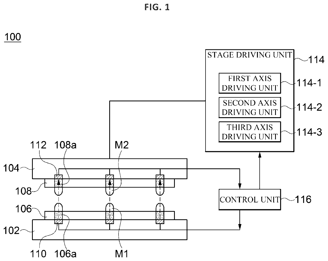
The present invention is about a way to automatically align two substrates together, using a light emitting unit and a light receiving unit. This helps to bring viscous materials on each substrate into precise contact with each other, which improves the fabrication of small needles and reduces time and costs.

Problems solved by technology

However, when the microneedles are manufactured using the molding technique, the microneedles may be damaged in the process of separating a patch having the microneedles formed thereon from the molds, or the fabricated microneedles have week strength.
However, even in the drawing technique, it is difficult to precisely align positions of viscous materials on an upper plate and a lower plate.

Method used

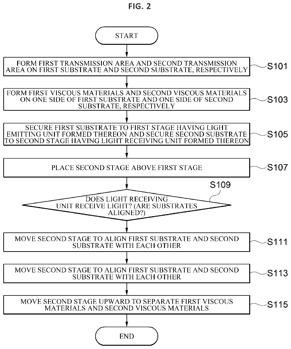

Image

  • Apparatus and method for manufacturing microneedle
  • Apparatus and method for manufacturing microneedle
  • Apparatus and method for manufacturing microneedle

Examples


Embodiment Construction

[0021]Hereinafter, detailed embodiments of the present invention will be described with reference to the accompanying drawings. The following detailed description is provided for a more comprehensive understanding of methods, devices and / or systems described in this specification. However, the methods, devices, and / or systems are only examples, and the present invention is not limited thereto.

[0022]In the description of the present invention, detailed descriptions of related well-known functions that are determined to unnecessarily obscure the gist of the present invention will be omitted. Some terms described below are defined in consideration of functions in the present invention, and meanings thereof may vary depending on, for example, a user or operator's intention or custom. Therefore, the meanings of terms should be interpreted based on the scope throughout this specification. The terminology used in the detailed description is provided only to describe embodiments of the pres...


PUM

PropertyMeasurementUnit
Timeaaaaaaaaaa
Viscosityaaaaaaaaaa
Areaaaaaaaaaaa

Abstract

An apparatus for fabricating a microneedle includes a first substrate having a plurality of first spaced viscous materials formed on one side thereof and including at least one first transmission area, a second substrate disposed opposite to the first substrate, having a plurality of second spaced viscous materials formed on one side thereof facing the first substrate and including at least one second transmission area corresponding to the first transmission area, a light emitting unit arranged to correspond to the first transmission area on the other side of the first substrate and emitting light, and a light receiving unit arranged to correspond to the second transmission area on the other side of the second substrate. The microneedle manufacturing apparatus checks whether the first substrate and the second substrate are aligned according to whether the light receiving unit receives light emitted from the light emitting unit.

Description

TECHNICAL FIELD[0001]The present invention relates to microneedles.BACKGROUND ART[0002]Microneedle is a new technology that enables painless delivery of growth hormones, insulin, vaccines, protein treatments, and the like, which are difficult to orally administered, through the skin. Microneedle technology is applicable to various applications, such as high functional cosmetic materials, drugs, medicines and medical devices.[0003]Conventionally, microneedles are fabricated by a molding technique. However, when the microneedles are manufactured using the molding technique, the microneedles may be damaged in the process of separating a patch having the microneedles formed thereon from the molds, or the fabricated microneedles have week strength. Hence, an attention has recently been paid to a drawing technique, which has overcome the limitations of the molding technique. In the drawing technique, microneedles are fabricated by drawing up and tensioning viscous materials. However, even...

Claims


Application Information

Patent Timeline
IPC IPC(8): B29C67/00A61M37/00
CPCB29C67/0003B29L2031/7544A61M2037/0053A61M37/0015B29L2031/756
Inventor LEE, DONG INLEE, DONG SUKIM, BONG HWANKANG, EUN JU
Owner RES COOPERATION FOUND OF YEUNGNAM UNIV
Why Eureka
Eureka Blog
Learn More