
Ignition suppressing enclosure having vent paths for flame quenching

a technology of vent paths and enclosures, applied in fire rescue, medical science, dental surgery, etc., can solve the problems of increased container overall cost, difficult testing of leak-proof containers, and long leak-proof requirements

Pending Publication Date: 2021-09-23
THE BOEING CO
View PDF2 Cites 0 Cited by
  • Summary
  • Abstract
  • Description
  • Claims
  • Application Information

AI Technical Summary

Benefits of technology

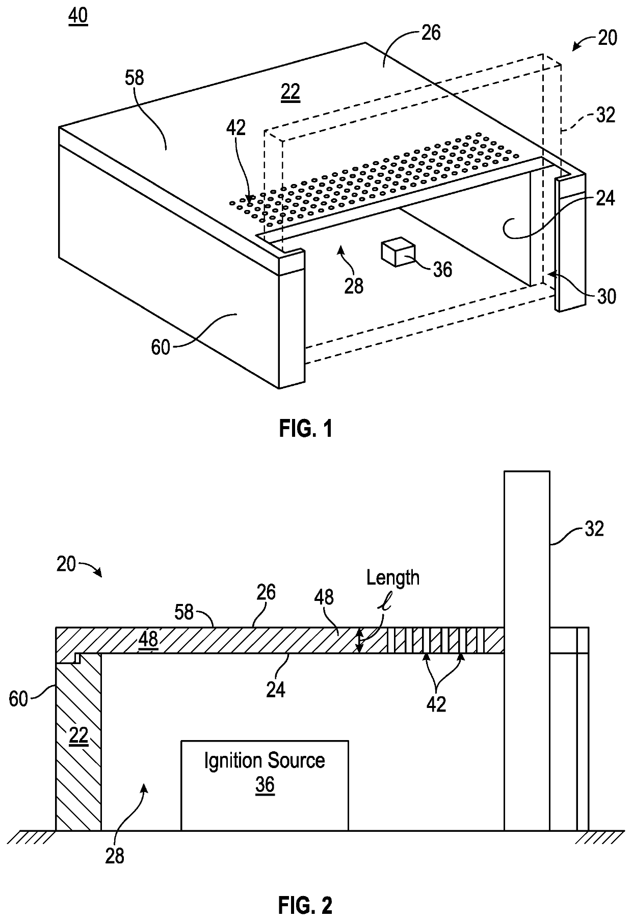
The patent describes an ignition suppressing enclosure and a method for using it to prevent an ignition source from igniting a combustible environment. The enclosure contains a flammable gas mixture and is surrounded by a larger combustible environment. The enclosure has vent paths that allow the gas to pass through, with the effective diameter of each path being large enough to quench a flame. The gas then flows into the surrounding combustible environment. The technical effect of this invention is to provide a safe way to handle ignition sources in potentially dangerous environments.

Problems solved by technology

However, this approach the leak-proof requirement lasts for the lifetime of the container.
The leak-proof container may also be difficult to test.
All of these issues increase the overall cost of the container.
Although alternative approaches exist for providing explosion-proof equipment, these methodologies also have drawbacks.
However, providing redundant electrical connectors increases the overall costs of the equipment.
Moreover, redundant electrical connectors are rarely relied upon as the sole approach for preventing an ignition source from propagating to a flammable environment.

Method used


Image

  • Ignition suppressing enclosure having vent paths for flame quenching
  • Ignition suppressing enclosure having vent paths for flame quenching
  • Ignition suppressing enclosure having vent paths for flame quenching

Examples


Embodiment Construction

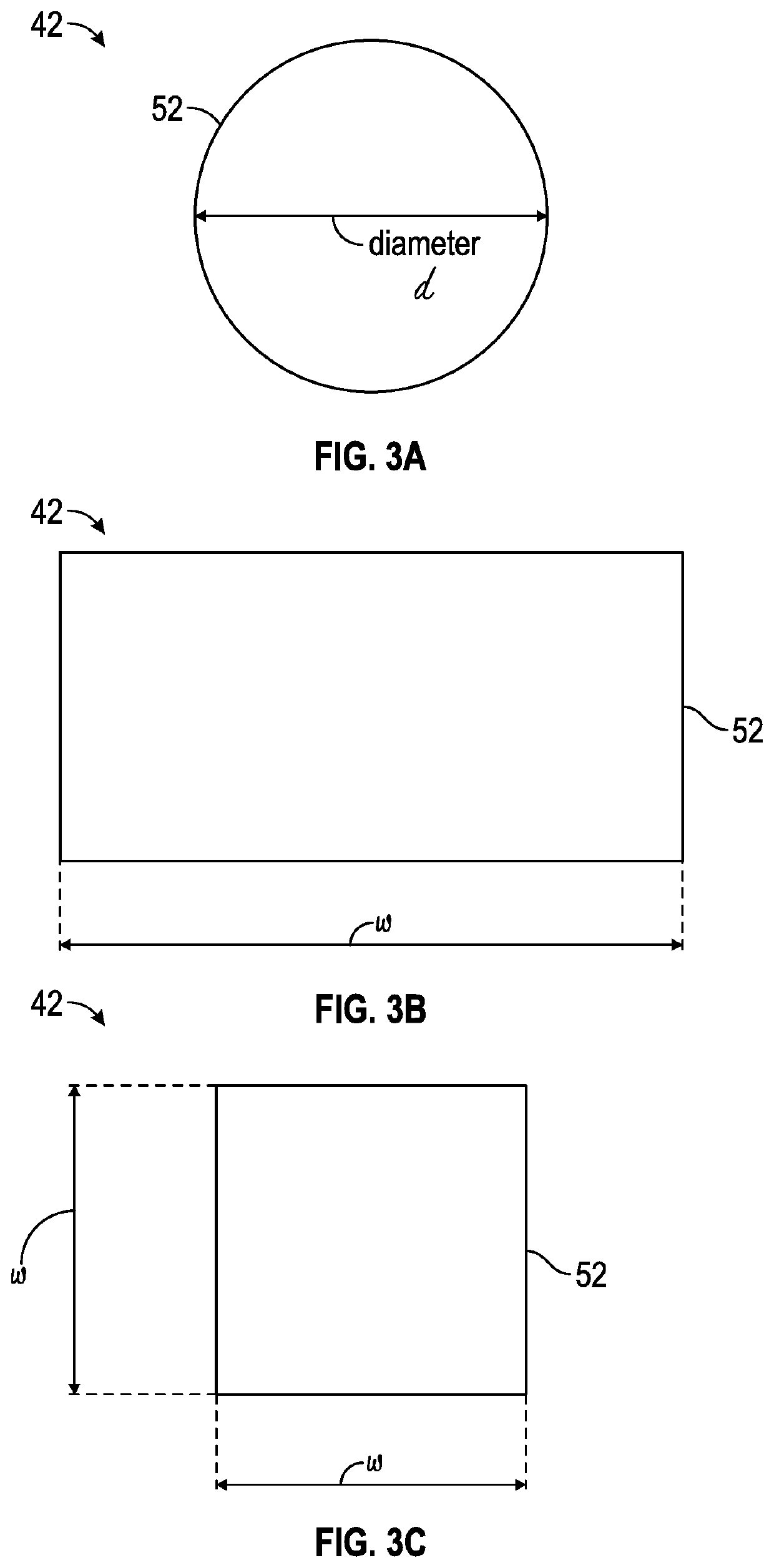
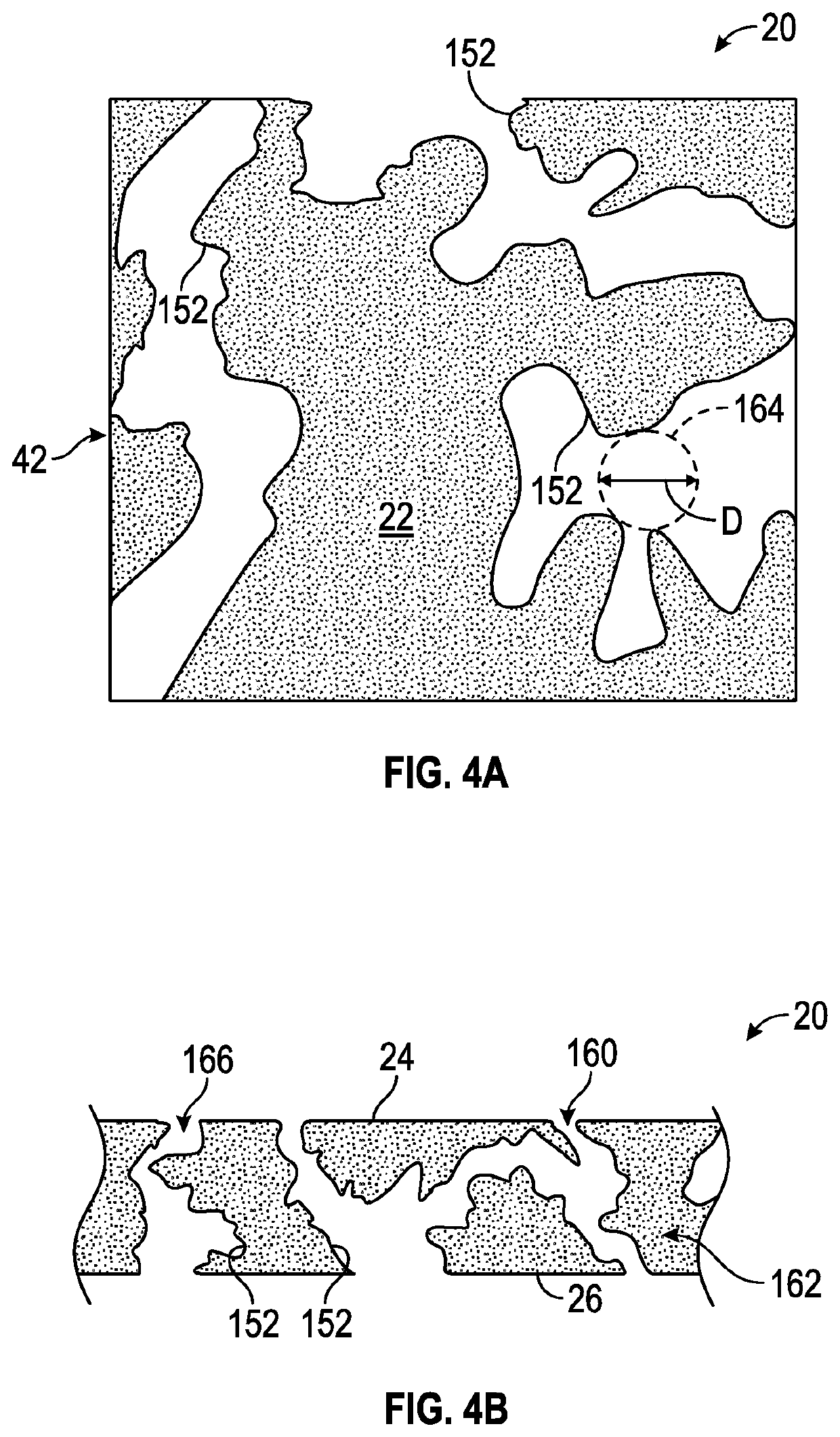
[0017]The present disclosure is directed towards an ignition suppressing enclosure, where an ignition source is placed within an enclosed volume of the ignition suppressing enclosure. The enclosed volume of the ignition suppressing enclosure as well as the exterior combustible environment surrounding the ignition suppressing enclosure both contain a flammable gaseous mixture. The ignition suppressing enclosure includes one or more vent paths disposed between an inner surface and an outer surface of a wall of the ignition suppressing enclosure. Each individual vent path includes an effective diameter based on at least a minimum ignition energy of the flammable gaseous mixture surrounding the ignition suppressing enclosure. The effective diameter of the individual vent path is selected to quench a flame that occurs within the enclosed volume of the ignition suppressing enclosure. In other words, the disclosed ignition suppressing enclosure includes one or more vent paths that ensure t...


PUM


Abstract

An ignition suppressing enclosure configured to contain an ignition source is disclosed and includes a body portion defining an inner surface, an outer surface, and an enclosed volume containing a flammable gaseous mixture. The enclosed volume is sized to contain the ignition source. The enclosed volume of the ignition suppressing enclosure is surrounded by an exterior combustible environment also containing the flammable gaseous mixture. The ignition suppressing enclosure includes one or more vent paths that extend between the inner surface and the outer surface of the body portion, where each individual vent path includes an effective diameter based on at least a minimum ignition energy of the flammable gaseous mixture. The effective diameter of the individual vent path is selected to quench a flame that occurs within the enclosed volume of the ignition suppressing enclosure.

Description

INTRODUCTION[0001]The present disclosure relates to an ignition suppressing enclosure. More particularly, the present disclosure is directed towards an ignition suppressing enclosure having one or more vent paths configured to quench a flame occurring within an enclosed volume of the ignition suppressing enclosure.BACKGROUND[0002]Explosion-proof equipment is required in a flammable environment. For example, explosion-proof equipment is required in flammability zones around an aircraft when the aircraft's fuel tank is being purged. In one approach, a leak-proof container that hydraulically isolates an interior environment from a flammable exterior combustible environment may be used as an explosion-proof container. Therefore, if the equipment located within the leak-proof container produces an ignition source, the surrounding exterior combustible environment does not ignite. However, this approach the leak-proof requirement lasts for the lifetime of the container. Moreover, the leak-...

Claims


Application Information

Patent Timeline
IPC IPC(8): A62C2/06A62C3/16
CPCA62C2/06A62C3/16A62C4/00
Inventor DAMAZO, JASON SKWON, EDDIESWEET, WILLIAM JBOETTCHER, PHILIPP A.
Owner THE BOEING CO
Learn More