
Prefabricated tuned top and launcher for launching tuned top

a tuned top and launcher technology, applied in the direction of toys, toys, entertainment, etc., can solve the problems of difficult assembly, complicated structure, and limited use of string tops, so as to prevent the diminishment of an initial spinning power, facilitate assembly, and enjoy the effect of the top

Active Publication Date: 2021-09-23
KIM YONG CHEOL
View PDF12 Cites 0 Cited by
  • Summary
  • Abstract
  • Description
  • Claims
  • Application Information

AI Technical Summary

Benefits of technology

The present invention is a prefabricated tuned top that can be easily assembled, changed spinning form, and safely, semi-permanently, and easily enjoyed at any location. The top has a spring embedded therein to buffer the spindle of the top and can prevent damage to the floor and initial spinning power. The rim of the top has various shapes, and the invention does not have the retaining jaw of the hook shape of the conventional top, which prevents unintended separation or bad separation of the top.

Problems solved by technology

Because of the above-mentioned differences, there are limitations in utilizing as the string top, the launcher top or the finger top.
However, since the string top has no knob and the launcher top has a knob changed in structure for gear meshing, the string top and the launcher top are inappropriate for spinning by the finger.
However, the top disclosed in Japanese Patent Laid-open No. 2000-197776 has several disadvantages in that it is complicated in structure and it is difficult to assemble since the top must have a suspension unit, and a fastening screw and an adjusting screw for fastening the suspension unit, must be specified in location of the top, and must have a coupling structure to screw the head member and the bottom member to the body member.
Additionally, the string top which is not usable as the finger top has a string to be wound on the body member.
It is difficult to miniaturize the top like the finger top with the size of less than 3 cm due to the complicated structure.
However, because the top disclosed in Japanese Utility Model Registration No. 3088350 is clarified as the launcher top spinning by a shooter, it is difficult to be used as a finger top based on the concept of the Table 1.
As described above, the top disclosed in Japanese Utility Model Registration No. 3088350 has several disadvantages in that it is complicated and difficult to mold since having the magnetic core, a space for mounting the magnetic core, the magnet embedded therein, and the arrangement that the magnetic core gets in contact with the magnet, and since a lower layer member, a middle layer member and an upper layer member must be molded to have a specific fitting assembly structure, and in that it is structurally inconvenient to assemble since having additional insertion pieces and a storage part.
On the contrary, because the finger top has a long knob but does not have a gear mesh structure, it cannot be fit and used to the shooter, thus it is difficult for the launcher top and the finger top to be redirected to each other.
So, the string top is utterly different from the finger top in concept, increases manufacturing costs due to the complicated structure of a bundle of spinning spindles for fixing the spring, and it is difficult to fit a coupling protrusion of the body to an outer ring at the time of assembly.
Therefore, the top is out of the balance and does not frequently well, so the user has to repeat a launching action several times.
However, the conventional art cannot solve the above-mentioned demerits other than the above.
However, if the top is fixed too tightly, the top is not separated easily.
On the contrary, if the top is fixed loosely, the top is easily separated from the launcher due to weak fixation power before launching.
Moreover, in this case, even though the top is fixed, due to looseness, the top cannot obtain a strong spinning power, so it reduces fun and it is tiresome and complicated since the user has to launch the top several times.
Because most of the launcher tops are made of synthetic resin, the retaining jaw is worn down when being used for a long time, and it causes deterioration of retaining power and reduction of lifespan of the top.
Additionally, because the conventional top is a single type top that only one top is fit to one launcher, the launcher top is very monotonous, and the top launched can spin jus in one direction.
So, the conventional launcher top has a limitation that it cannot provide fun of various and changeable games.
Moreover, because the conventional tops are manufactured in a state where the center of gravity is settled according to standards, users cannot increase or decrease the center of gravity as the user please.
That is, because the users cannot adjust the width of precession as the users want, the conventional tops has a limitation in realizing an attacking style top suitable for user preferences.
Furthermore, because the rack gear of the conventional launcher is formed at one side, the rack gear has directivity, so users feel inconvenient since they have to fit the top to a launcher body while checking all parts.

Method used


Image

  • Prefabricated tuned top and launcher for launching tuned top
  • Prefabricated tuned top and launcher for launching tuned top
  • Prefabricated tuned top and launcher for launching tuned top

Examples


first embodiment

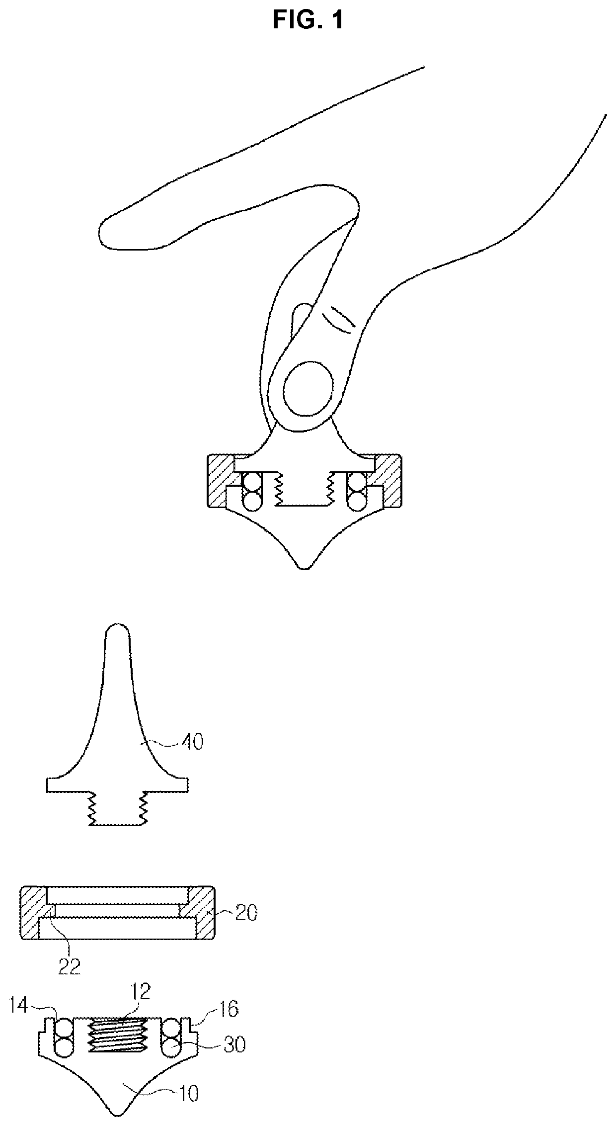
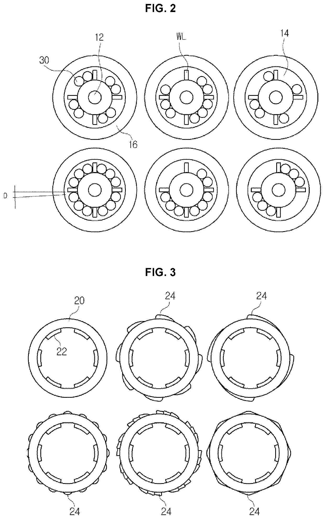
[0091]In this instance, the body 10, the rim 20, the iron beads 30, and the knob 40 are in the same category as the first embodiment described above.

[0092]The top according to the second embodiment of the present invention includes all of the parts of the first embodiment as they are.

[0093]However, some parts of the body 10 are transformed in order to mount the spinning spindle 50, and the transformed parts will be described.

[0094]That is, a spindle hole HOL is formed from an upper end to a bottom end at the center of the body 10, namely the center of a screw groove 12. The spindle hole HOL has a structure that a large diameter and a small diameter are formed from the upper end to the bottom end to communicate with each other to have a stepped portion therebetween.

[0095]Therefore, a T-shaped spinning spindle 50 is assembled to be retained and fixed to the spindle hole HOL after being inserted into the spindle hole HOL.

[0096]Then, a portion of the bottom end of the spinning spindle 5...

second embodiment

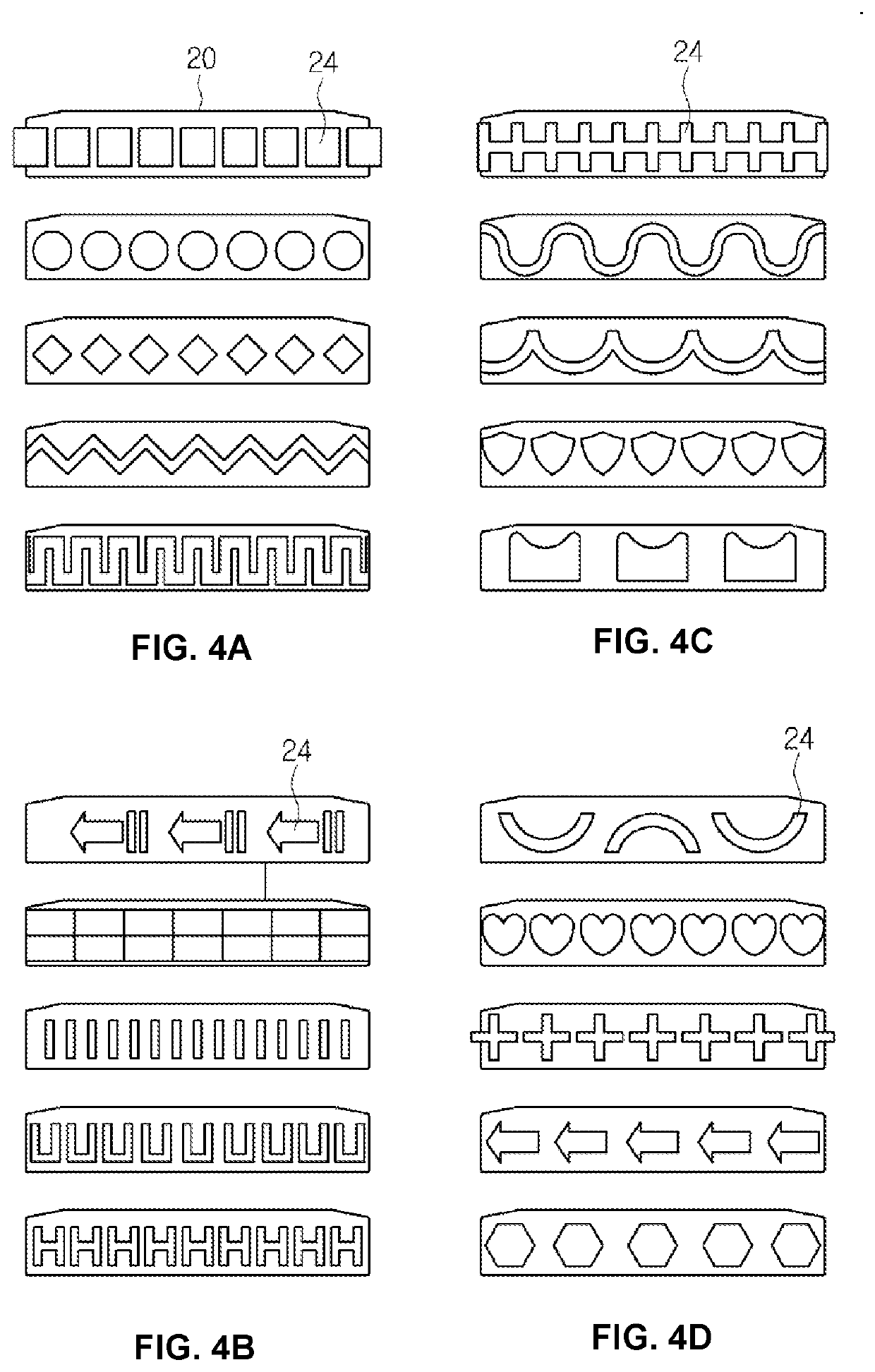
[0097]The finger top according to the present invention may be modified in various ways as shown in FIGS. 8 and 9 so as to provide various esthetic senses and functions.

[0098]Especially, referring to FIG. 8, the description of the structure of the knob 50 will quote description of the first embodiment.

[0099]In the meantime, a prefabricated tuned top capable of spinning by a launcher may have the form illustrated in FIGS. 10 to 12 so as to be combined with the launcher.

[0100]As shown in FIGS. 10 to 12, the launcher 200 includes: a lower base 210 having a knob insertion hole 212 formed at the center and winder insertion grooves 214 formed at one side or both sides in such a way that the knob insertion hole 212 is interposed therebetween; an upper base 230 matching the lower base 210 to be opposed to the lower base 210; and a winder 220 fit into the winder insertion groove 214.

[0101]In this instance, the winder 220 is a plate-shaped band having rack gears 222 formed at both sides there...


PUM


Abstract

A prefabricated tuned top and a launcher for launching the tuned top, manufactured in a small size with five components of a knob, a rim, beads, a body and a spinning spindle. The tuned top can be readily assembled by sequentially inserting and then tightening the components. The tuned top implements a changeable spinning form based on induction of a change in difference between the centripetal force and centrifugal force, generated during spinning, since the center of gravity can be eccentrically disposed freely according to the user's selection. The tuned top is prevented from being reversely loosened so it can be safely, semi-permanently, and easily enjoyable at any location. The tuned top enables accurate and stable mounting when a launcher is used, such that the top is not easily separated therefrom but is quickly launched without a launch failure, thereby providing accurate launching without the loss of spinning power.

Description

RELATED APPLICATION[0001]This application is a § 371 application of PCT / KR2019 / 005713 filed May 13, 2019, which claims priority from Korean Patent Application No. 10-2018-0082768 filed Jul. 17, 2018 and No. 10-2018-0109577 filed Sep. 13, 2018, each of which is incorporated herein by reference in its entirety.TECHNICAL FIELD[0002]The present invention relates to a prefabricated tuned top and a launcher for launching the tuned top and, more specifically, to a prefabricated tuned top and a launcher for launching the tuned top, which: can be simply manufactured in a small size with only the five components of a knob, a rim, beads, a body and a spinning spindle; can be very easily assembled just by sequentially inserting and tightening the components; can implement a changeable spinning form by inducing a change in the difference between centripetal force and centrifugal force, which are generated during spinning, since the center of gravity can be eccentrically disposed freely according...

Claims


Application Information

Patent Timeline
Patent Type & Authority Applications(United States)
IPC IPC(8): A63H1/04A63H1/10A63H31/06
CPCA63H1/04A63H31/06A63H1/10A63H1/00A63H1/18
Inventor KIM, YONG CHEOL
Owner KIM YONG CHEOL
Learn More