Method for controlling an electronically slip-controllable power braking system of a motor vehicle, electronically slip-controllable power braking system, and electronic control unit

a technology of power braking system and electronic control unit, which is applied in the direction of braking system, braking components, electric devices, etc., can solve the problems of increasing drive speed, reducing the torque generated, and not having sufficient generator braking torque to decelerate the vehicle to a standstill, so as to prevent the buildup of brake pressure

Pending Publication Date: 2021-09-23
ROBERT BOSCH GMBH
View PDF3 Cites 0 Cited by
  • Summary
  • Abstract
  • Description
  • Claims
  • Application Information

AI Technical Summary

Benefits of technology

[0011]The present invention may have the advantage that the occupants of the vehicle perceive preferably little feedback or none at all when the braking system changes from the generator braking operation to the friction braking operation. The latter is achieved according to the present invention by an electrical activation optimized in this regard of drive unit 40 of brake pressure generator 30 by electronic control unit 16 of power braking system 10.
[0015]A smoother beginning and a smoother end of the actuation are achieved by the provided optimization of the activation. Occurring accelerations of the displacer are thus reduced, the change of the brake pressure is reduced, and finally the driving comfort is enhanced for the vehicle occupants by avoidance of perceptible noises and vibrations.
[0019]The present invention prevents a brake pressure buildup from taking place in an annoyingly perceptible manner, even in the case of high pressure buildup dynamics. In addition, pressure oscillations are avoided, which result in deceleration variations of the vehicle in spite of an existing constant braking intention.

Problems solved by technology

However, the generator braking torque generated is dependent on the drive speed of the generator and decreases with decreasing drive speed.
If the vehicle velocity and thus the drive speed of the generator is excessively low, sufficient generator braking torque is not available to be able to decelerate the vehicle to a standstill.
These mechanically stress displacer 32 and its drive, and cause noises or vibrations which may be perceived as annoying by the vehicle occupants.

Method used


Image

  • Method for controlling an electronically slip-controllable power braking system of a motor vehicle, electronically slip-controllable power braking system, and electronic control unit
  • Method for controlling an electronically slip-controllable power braking system of a motor vehicle, electronically slip-controllable power braking system, and electronic control unit

Examples


Embodiment Construction

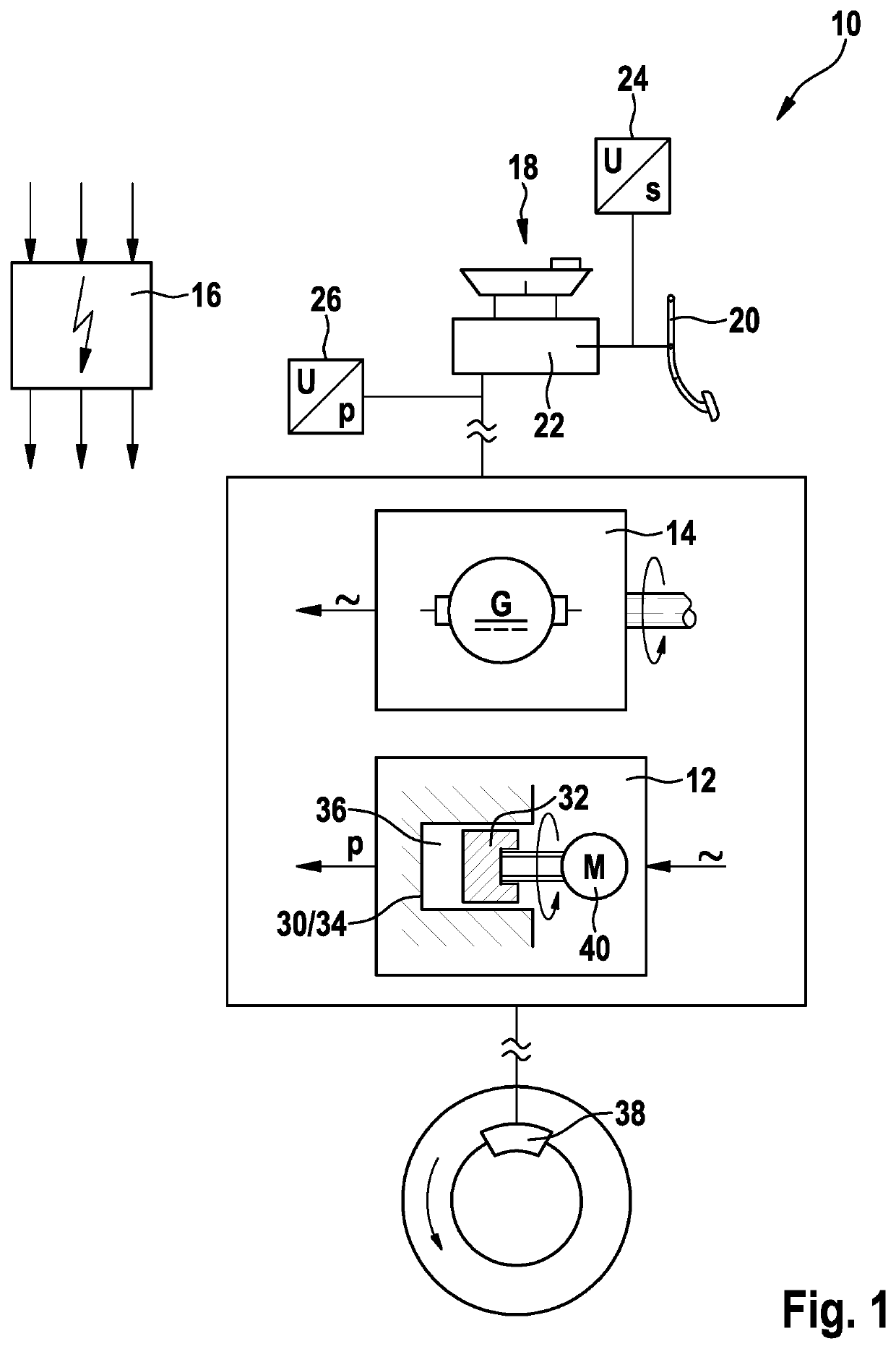
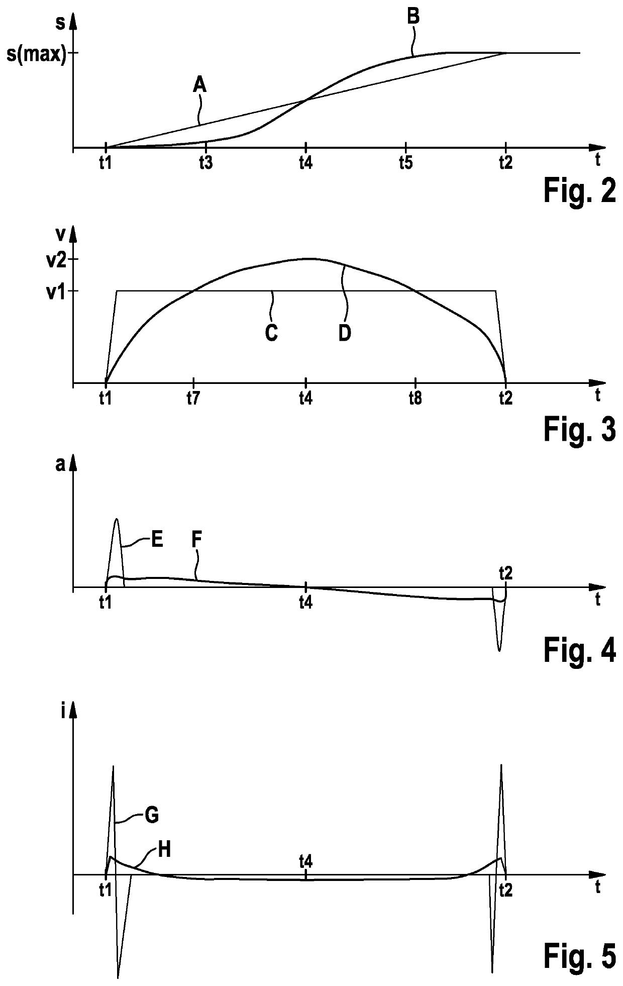
[0024]The diagram shown in FIG. 2 indicates the curve of travel s covered by displacer 32 or piston of brake pressure generator 30 over time t of a braking process taking place, after a change has taken place of power braking system 10 from generator braking operation to friction braking operation. Two characteristic curves A, B are shown, of which characteristic curve A continuously rises from a starting point t1, at which covered travel s is zero, at constant slope up to an end point t2, at which maximum travel s(max) has been covered. This characteristic curve corresponds to the activation method known from the related art for drive unit 40 of brake pressure generator 30. In this activation method, displacer 32 moves between the endpoints at constant velocity (see FIG. 3).

[0025]In contrast thereto, characteristic curve B shows an s-shaped curve between endpoints t1 and t2. Characteristic curve B indicates the movement of displacer 32 which results when brake pressure generator 30...


PUM


Abstract

A method for controlling an electronically slip-controllable power braking system, an electronically slip-controllable power braking system, and an electronic control unit of an electronically slip-controllable power braking system. The power braking system has a friction braking device, a generator braking device, and an electronic control unit for controlling the braking devices adapted to need. The friction braking device includes an electronically activatable brake pressure generator including a displacer which is actuatable by an activatable drive unit and conveys pressure medium to a wheel brake of the power braking system. After a change of the power braking system from generating a generator braking torque to generating a friction braking torque, the activation of the drive unit of the displacer is carried out by the electronic control unit in such a way that a velocity of the actuated displacer changes strictly monotonously.

Description

CROSS REFERENCE[0001]The present application claims the benefit under 35 U.S.C. § 119 of German Patent Application No. DE 102020203581.4 filed on Mar. 20, 2020, which is expressly incorporated herein by reference in its entirety.FIELD[0002]The present invention relates to a method for controlling an electronically slip-controllable power braking system of a motor vehicle, an electronically slip-controllable power braking system, and an electronic control unit.BACKGROUND INFORMATION[0003]Electronically slip-controllable power braking systems in motor vehicles are part of the related art. They are capable of carrying out braking processes independently of a braking intention of the driver and prevent locking wheels during driving operation, during starting, or during a braking process. Such power braking systems therefore contribute significantly to avoiding hazardous driving situations and ultimately to increasing the traffic safety.[0004]An electronically slip-controllable power bra...

Claims


Application Information

Patent Timeline
Patent Type & Authority Applications(United States)
IPC IPC(8): B60L7/18B60L3/10B60T13/74
CPCB60L7/18B60L3/10B60T2270/60B60L2240/423B60L2240/465B60T13/745B60T13/662B60L2240/421B60L7/22B60T13/586B60T2270/604Y02T10/64B60T13/74B60T13/585B60Y2400/81B60Y2306/09
Inventor LANG, MARKUSWOERZ, CHRISTIAN
Owner ROBERT BOSCH GMBH
Why Eureka
Try Eureka