Eureka AIR delivers breakthrough ideas for toughest innovation challenges, trusted by R&D personnel around the world.

Testing Device for the In Situ Determination of the Fracture Toughness of Glued Joints

Pending Publication Date: 2021-09-23
UNIV DE SEVILLA
View PDF0 Cites 0 Cited by
  • Summary
  • Abstract
  • Description
  • Claims
  • Application Information

AI Technical Summary

Benefits of technology

The invention is a small and flexible testing device that can be taken to the actual location where a glued joint needs to be evaluated. This makes it easier, faster, and less risky to determine if the joint is sound.

Problems solved by technology

The main problems existing in the tests performed under the standard are as follows:the need to generate specific specimens to perform the test in a laboratory, determining the need to manufacture parts in addition to those required for making the corresponding structure.Whether or not the glued structural part is suitable is not immediately known, and furthermore the specimen to be tested is obtained from another 002E part.

Method used


Image

  • Testing Device for the In Situ Determination of the Fracture Toughness of Glued Joints
  • Testing Device for the In Situ Determination of the Fracture Toughness of Glued Joints
  • Testing Device for the In Situ Determination of the Fracture Toughness of Glued Joints

Examples


first embodiment

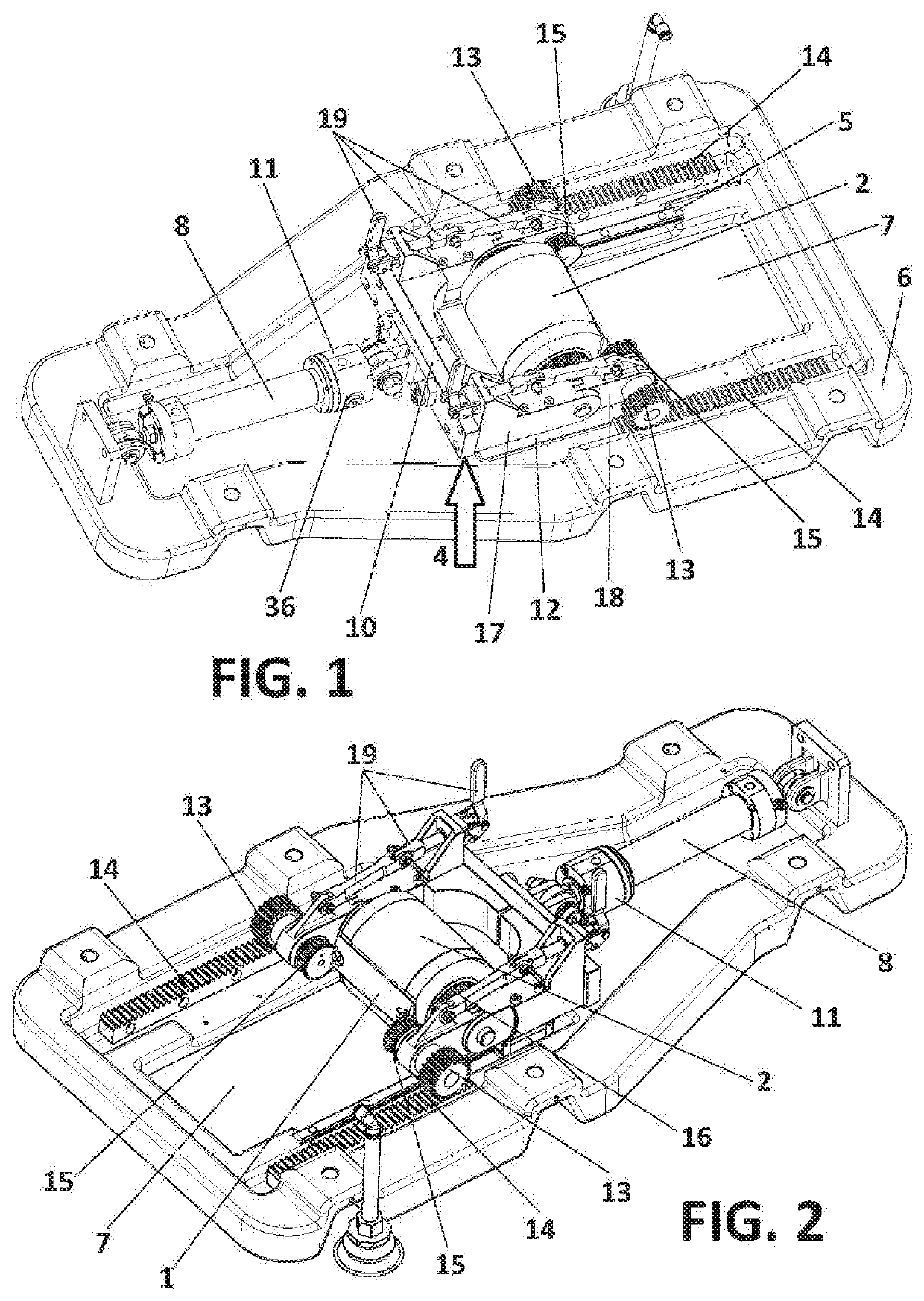
[0024]FIG. 1 shows a perspective view of the testing device.

[0025]FIG. 2 shows a detailed perspective view of the first embodiment of the testing device.

second embodiment

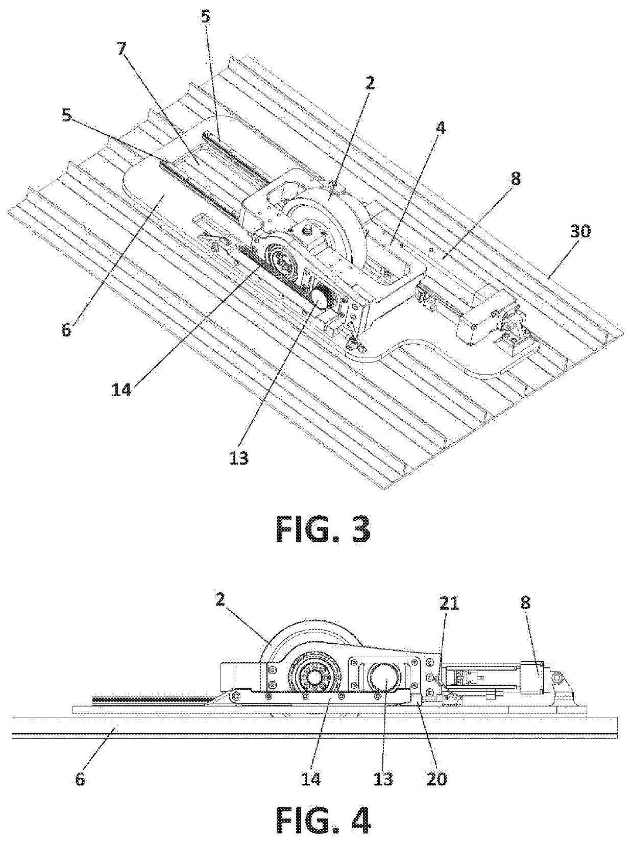
[0026]FIG. 3 shows a perspective view of the testing device.

[0027]FIG. 4 shows a side view of a second embodiment of the testing device.

third embodiment

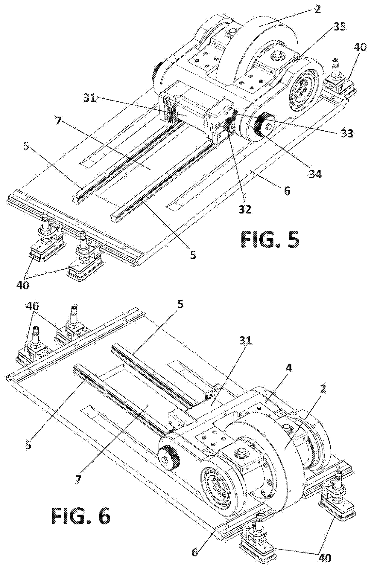
[0028]FIG. 5 shows a perspective view of the testing device.

[0029]FIG. 6 shows an elevational view of a third embodiment of the testing device.

[0030]FIG. 7 shows a schematic view in which the drum is seen in motion, stripping off the upper component of a specimen made of a hybrid material joined by means of an adhesive.


PUM

PropertyMeasurementUnit
Fracture toughnessaaaaaaaaaa
Electrical resistanceaaaaaaaaaa

Abstract

The invention relates to a testing device that can be transported and used in situ on a structure to be tested to determine the resistance thereof to peeling. The device fundamentally comprises: a drum with attachment elements for attaching to a specimen that is to be peeled from a hybrid adhesive joint of a structure, a movable carriage on which the drum is mounted; a frame along which the drum moves; and an actuation mechanism that determines the linear movement of the carriage or the rotational movement of the drum and which, by the reaction of the specimen, determines, respectively, the rotation of the drum or the linear displacement of the carriage.

Description

OBJECT OF THE INVENTION[0001]The present invention relates to a testing device of particular interest in the aerospace sector.[0002]The testing device object of this invention is portable and versatile, which allows it to be transported and used in situ on an actual part where the glued joint that is to be evaluated is located, thereby reducing costs, time, and uncertainties.BACKGROUND OF THE INVENTION[0003]Ensuring the quality of a glued joint is a concern of the scientific community and industry, wherein said concern is particularly noted in the aerospace sector in which the use of composite-composite glued joints is constantly on the rise.[0004]More and more composite materials, whose properties, such as specific density, mechanical properties, complex geometry adaption capacity, absence of corrosion, reduced maintenance costs, thermal and sound insulation, are well known, are employed in structures used in aerospace components.[0005]The manufacturing processes are extremely expe...

Claims


Application Information

Patent Timeline
IPC IPC(8): G01N19/04
CPCG01N19/04G01N2203/0676G01N2203/0067G01N2203/0037G01N2203/0091A47J47/14B65D65/403Y02W30/80B32B3/12B32B27/10B32B27/30B32B2307/304B32B2307/726B32B2439/62B65D65/40B65D81/3818
Inventor CANAS DELGADO, JOSEPARIS CARBALLO, FEDERICOTAVARA MENDOZA, LUISBLAZQUEZ GAMEZ, ANTONIOESTEFANI MORALES, ALEJANDROSANTACRUZ RODRIGUEZ, GLORIASTOVEN, TIMO
Owner UNIV DE SEVILLA
Why Eureka
Eureka Blog
Learn More