Unlock instant, AI-driven research and patent intelligence for your innovation.

Object detection apparatus and movable apparatus

Pending Publication Date: 2021-09-23
RICOH KK
View PDF0 Cites 0 Cited by
  • Summary
  • Abstract
  • Description
  • Claims
  • Application Information

AI Technical Summary

Benefits of technology

The patent text describes an object detection apparatus that uses light to scan for objects in a detection region. The apparatus includes a light-emitting unit, an optical scanning unit, a light-projection optical system, a light-receiving optical system, and a light receiving unit. The detection is made by measuring reflected or scattered light from the object in the detection region. The apparatus has a unique design with a non-parallel projection light center axis and a receiving light center axis, which improves the detection of objects.

Problems solved by technology

However, as to the one object detection apparatus, a scanning angle of the scanning light may be limited due to a size of the deflection face, and the strength of deflection face may not be ensured.

Method used


Image

  • Object detection apparatus and movable apparatus
  • Object detection apparatus and movable apparatus
  • Object detection apparatus and movable apparatus

Examples


first embodiment

(Configuration of Object Detection Apparatus)

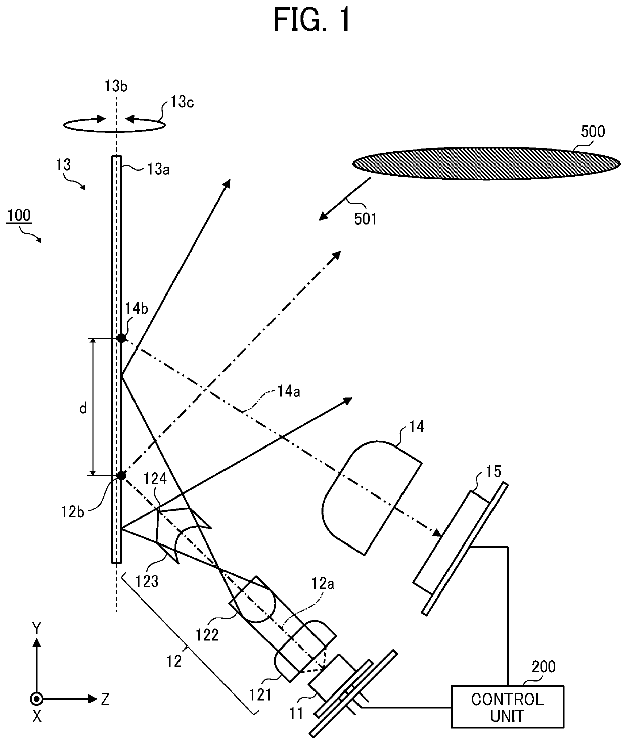
[0035]FIG. 1 is an example of a configuration of the object detection apparatus 100 according to a first embodiment. As illustrated in FIG. 1, the object detection apparatus 100 includes, for example, a semiconductor laser 11, a light-projection optical system 12, a micro electro mechanical systems (MEMS) mirror 13, a light-receiving optical system 14, a photodiode 15, and a control unit 200.

[0036]The semiconductor laser 11 is a light-emitting unit that emits laser light or laser beam. The semiconductor laser 11 can emit laser light at a given light emission timing in response to a control signal received from the control unit 200. The laser light is an example of “light.” The laser light may be pulse laser light or continuous wave (CW) laser light.

[0037]Although the wavelength of the laser light projected from the semiconductor laser 11 is not particularly limited, when the object detection apparatus 100 is mounted on an automobile or th...

second embodiment

[0141]Hereinafter, with reference to FIG. 7, a description is given of an object detection apparatus 100a according to a second embodiment. FIG. 7 is an example of functional block diagram of the control unit 200a provided for the object detection apparatus 100a.

[0142]As illustrated in FIG. 7, the control unit 200a includes, for example, a distortion correction unit 206, an object image information acquisition unit 207, a complementary object information acquisition unit 208, and a complementary object information output unit 209.

[0143]The functions of the distortion correction unit 206, the object image information acquisition unit 207, and the complementary object information acquisition unit 208 are implemented by executing one or more programs by the CPU 21 of FIG. 2. Further, the function of the complementary object information output unit 209 is implemented by the input / output I / F 28 of FIG. 2.

[0144]The distortion correction unit 206 receives a right-eye image captured by a r...

third embodiment

[0158]Hereinafter, with reference to FIG. 8, a description is given of a movable apparatus according to a third embodiment. FIG. 8 is an example of configuration of a movable apparatus 1 including the object detection apparatus 100. The movable apparatus 1 is, for example, an unmanned transport vehicle that transports a luggage to a destination.

[0159]The object detection apparatus 100 is disposed at the front of the movable apparatus 1 to acquire object information, such as distance image on the positive side of

[0160]Z-direction of the movable apparatus 1. The information output from the object detection apparatus 100 can be used to detect whether an object, such as obstacle, exists in the positive side of Z direction, and to detect a position of the object as object information.

[0161]FIG. 9 is an example of hardware block diagram of the movable apparatus 1.

[0162]As illustrated in FIG. 9, the movable apparatus 1 includes, for example, the object detection apparatus 100, a display de...


PUM


Abstract

An object detection apparatus includes a light-emitting unit configured to emit light; an optical scanning unit configured to rotate a deflection face to deflect the light used as scanning light; a light-projection optical system configured to project the scanning light to a detection region; a light-receiving optical system configured to receive light reflected or light scattered from an object existing within the detection region, respectively as reflection light and scattered light; and a light receiving unit configured to output at least a received-light signal of the reflection light or a received-light signal of the scattered light received by the light receiving system. A projection light center axis of the light-receiving optical system is non-parallel with respect to a focusing light center axis of the light-projection optical system.

Description

CROSS-REFERENCE TO RELATED APPLICATION[0001]This application claims priority pursuant to 35 U.S.C. § 119(a) to Japanese Patent Application No. 2020-048417, filed on Mar. 18, 2020 in the Japan Patent Office, the disclosure of which is incorporated by reference herein in its entirety.BACKGROUNDTechnical Field[0002]This disclosure relates to an object detection apparatus, and a movable apparatus.Background Art[0003]Conventionally, object detection apparatuses, such as light detection and ranging, laser imaging detection and ranging (LIDAR) devices, mounted on a movable apparatuses, such as vehicle, are known. The object detection apparatus emits light to a detection region of a movable apparatus such as a front direction of the movable apparatus, and receives light reflected or scattered from an object existing in the detection region to detect presence or absence of the object and a distance to the object.[0004]Further, one object detection apparatus includes an optical scanning unit ...

Claims


Application Information

Patent Timeline
IPC IPC(8): G01S17/04G01S17/89G01S7/481
CPCG01S17/04G01S7/4817G01S17/89G01S17/48G01S17/86G01S17/931G01S7/4811G01S7/4814G01S7/4868G01S7/4918G01S17/08G02B27/0927G02B27/0955G01S17/42G01S17/46
Inventor NAKAMURA, KENTONAKAMURA, TADASHIKISHIWADA, JUNABE, ISSEI
Owner RICOH KK