Positioning and stabilising structure and system incorporating same

a technology of positioning stabilisation and structure, applied in the field of positioning stabilisation, can solve the problems of limiting the comfort and usability of the system, affecting the comfort of users at localised stress points, and previous systems may be difficult to adjust to allow wide application head sizes, etc., to achieve effective transfer, increase rigidity, and reduce the effect of force applied

Active Publication Date: 2021-09-30
RESMED LTD
View PDF10 Cites 7 Cited by
  • Summary
  • Abstract
  • Description
  • Claims
  • Application Information

AI Technical Summary

Benefits of technology

[0017]In some forms, the forehead support connector further comprises a forehead support rigidiser that provides rigidification to a portion of the forehead support connector. In some forms, the forehead support rigidiser provides rigidification to a portion of the forehead support connector located along the frontal region of the user's head. The extent and positioning of the forehead support rigidiser may assist in correct positioning of the display unit and relieve pressure being applied to the zygomatic bone of the user. In some forms, the forehead support rigidiser may be adjustable (angularly or translational) on other components of the forehead support connector, such as the strap of the forehead support connector, to allow fine positioning of the head-mounted display unit and assist in improving user comfort and fit.
[0018]In some forms, the positioning and stabilising structure further includes additional rigidisers which may bridge the rear support structure and the temporal connectors. In some forms, these additional rigidisers may assist in controlling the movement of the display unit about the rear support structure to further stabilise and support the system. In some forms, these additional rigidisers may limit hinging movement at the connection of the temporal connectors to the rear support structure. In some forms, these additional rigidisers may also extend through along the occipital region of the rear support structure to further anchor the display unit in its correct operational position. In some forms, these additional rigidisers may be adjustable (angularly or translational) on other components of the forehead support connector to further assist in comfort, adjustability, and fit.
[0019]In some forms, the positioning and stabilising structure may allow for upward, e.g., superior, pivoting movement of the display unit to allow for movement of the display unit to a non-operational position without removal of the positional and stabilising structure (e.g., flip-up version). In some forms, this pivoting arrangement may provide a release mechanism at the forehead support connector and / or provide limited hinging regions at the temporal connectors.
[0029]The positioning and stabilizing structure and / or the head-mounted display unit may be configured to help distribute contact forces from more sensitive regions of the user's face (forehead, upper cheeks below the eyes) to regions that are better suited to oppose a force applied. For example, the rear support structure may be sufficiently flexible to evenly and snugly engage the rear of the user's head, e.g., anchor on the occipital bone but above the neck muscles, and / or have increased rigidity in one or more portions to better support the load of the head-mounted display unit in a comfortable and sustainable manner. For example, the rear support structure may be made of a strap material (e.g., textile) that is breathable and flexible to allow it to adjust to the shape and / or size of the user's head, where certain parts of the strap material may be rigidized and / or a rigid portion added (e.g., sewn, laminated, clipped, inserted into a pocket, overmolded, and / or ultrasonically welded into place) to help maintain stability and offset a portion of the force applied to a portion of the patient's face via the head-mounted display unit.
[0030]In an example, the positioning and stabilizing structure and / or the head-mounted display unit may be configured to cooperatively work together to reduce the force applied to the patient's forehead and / or cheek bones, by effectively transferring those forces to the rear support and / or to the at least one connector or strap(s), and / or by simply distributing the forces from the head-mounted display unit more evenly along the head-mounted display unit and / or the rear support structure and / or the at least one connector or strap(s). This is done in a way that adds comfort and / or stability, e.g., to prevent the head-mounted unit from sliding down the user's face / forehead.

Problems solved by technology

Such systems have been prone to exert a clamping pressure on the user's face which can result in user discomfort at localised stress points.
Also, previous systems may be difficult to adjust to allow wide application head sizes.
Further, the display unit and associated positioning and stabilising structure are often heavy and difficult to clean, which further limit the comfort and usability of the system.

Method used


Image

  • Positioning and stabilising structure and system incorporating same
  • Positioning and stabilising structure and system incorporating same
  • Positioning and stabilising structure and system incorporating same

Examples


Embodiment Construction

[0045]Before the present technology is described in further detail, it is to be understood that the technology is not limited to the particular examples described herein, which may vary. It is also to be understood that the terminology used in this disclosure is for the purpose of describing only the particular examples discussed herein, and is not intended to be limiting.

[0046]The following description is provided in relation to various examples which may share one or more common characteristics and / or features. It is to be understood that one or more features of any one example may be combinable with one or more features of another example or other examples. In addition, any single feature or combination of features in any of the examples may constitute a further example.

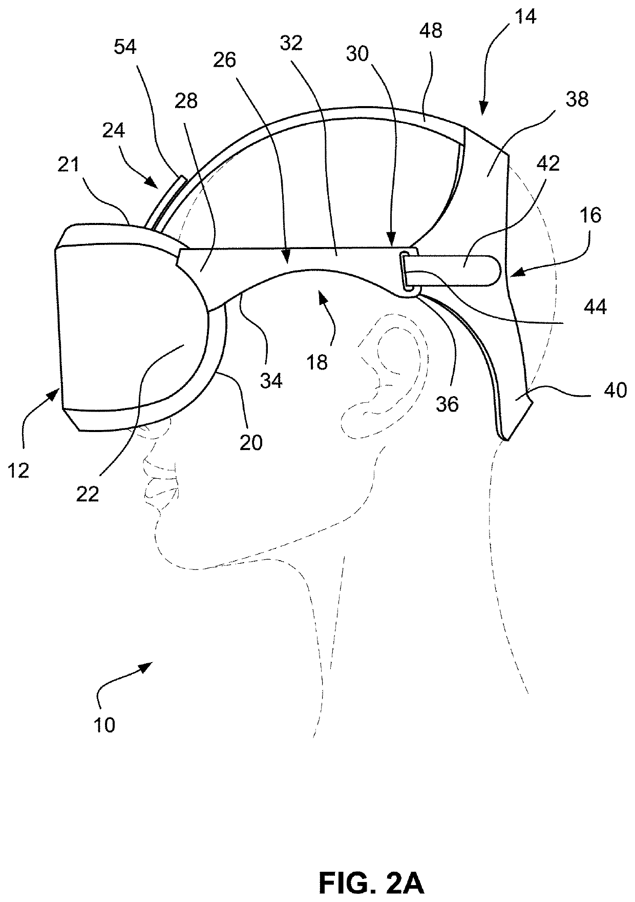
[0047]FIGS. 2A to 2C show a support for a head-mounted display system or assembly 10 according to a first example of the present technology. The head-mounted display system 10 comprises a head-mounted display unit...


PUM


Abstract

A head-mounted display system includes a head-mounted display unit and a positioning and stabilising structure structured and arranged to hold the head-mounted display unit in an operational position over a user's face in use. The positioning and stabilising structure includes a rear support structure adapted to contact posterior regions of a user's head and at least one connector structured and arranged to interconnect the rear support structure to the head-mounted display unit. The rear support structure is in the form of a hoop comprising an occipital portion configured and arranged engage the user's head along a portion of the occipital bone adjacent a junction where the neck muscles attach to the occipital bone in use.

Description

[0001]A portion of the disclosure of this patent document contains material which is subject to copyright protection. The copyright owner has no objection to the facsimile reproduction by anyone of the patent document or the patent disclosure, as it appears in Patent Office patent files or records, but otherwise reserves all copyright rights whatsoever.CROSS-REFERENCE TO RELATED APPLICATIONS[0002]This application claims the benefit of Australian Provisional Application No. 2020900953, filed Mar. 27, 2020, which is incorporated herein by reference in its entirety.FIELD OF THE TECHNOLOGY[0003]The present technology relates to a positioning and stabilising structure to hold a head-mounted display unit and an associated head-mounted display assembly including a display unit and positioning and stabilising structure. The present technology finds particular application in the use of virtual reality head-mounted displays and is herein described in that context. However, it is to be appreci...

Claims


Application Information

Patent Timeline
Patent Type & Authority Applications(United States)
IPC IPC(8): G02B27/01G02B27/02
CPCG02B27/0176G02B27/028G02B2027/0154
Inventor LAW, IAN ANDREW
Owner RESMED LTD
Why Eureka
Try Eureka