
Pneumatic tire with noise damper, and method for manufacturing the same

a technology of pneumatic tires and noise dampers, which is applied in the field of pneumatic tires with noise dampers, can solve the problems of insufficient noise dampening performance (road noise reduction effect), deformation and damage of the noise damper itself, and achieve the effects of suppressing the occurrence of damage, wide cross-sectional area, and suppressing the deformation caused by stress during running

Pending Publication Date: 2021-10-07
SUMITOMO RUBBER IND LTD
View PDF0 Cites 0 Cited by
  • Summary
  • Abstract
  • Description
  • Claims
  • Application Information

AI Technical Summary

Benefits of technology

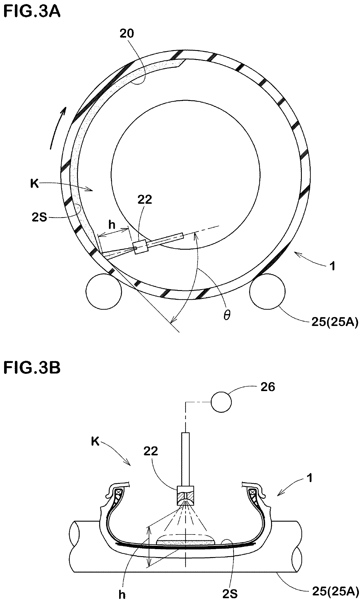
The first invention is about a noise damper made of porous resin foam that is designed to reduce damage and deformation during tire running. The noise damper is formed as a single annular body that continuously extends in the tire circumferential direction. The noise damper helps to prevent noise and vibrations from causing damage to the tire. The density of the noise damper is lower than the overall density of the tire, which allows for better durability. The second invention is about a method to produce the pneumatic tire with the noise damper, which involves applying a reaction mixture to the tire inner surface. This method improves work efficiency compared to the case where the noise damper is spirally wound multiple times. Overall, the invention provides a way to effectively reduce noise and vibrations during tire running.

Problems solved by technology

Moreover, in the case of the spiral noise damper, since a width of the noise damper itself is narrow, it has been found that the noise damper itself tends to be deformed and damaged by the stress received during running.
Further, it was also found that the cross-sectional area of the entire noise damper is small due to the continuous groove, therefore, noise dampening performance (road noise reduction effect) is not sufficiently exerted.

Method used


Image

  • Pneumatic tire with noise damper, and method for manufacturing the same
  • Pneumatic tire with noise damper, and method for manufacturing the same
  • Pneumatic tire with noise damper, and method for manufacturing the same

Examples


Embodiment Construction

[0032]An embodiment of the present invention will now be described in detail.

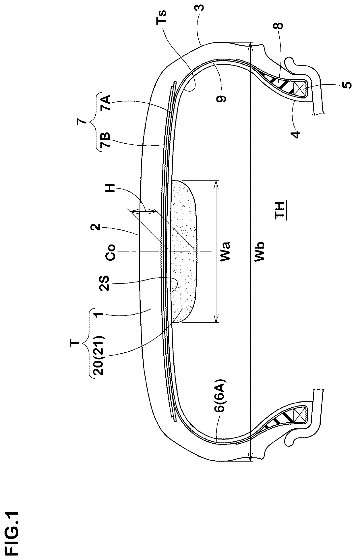
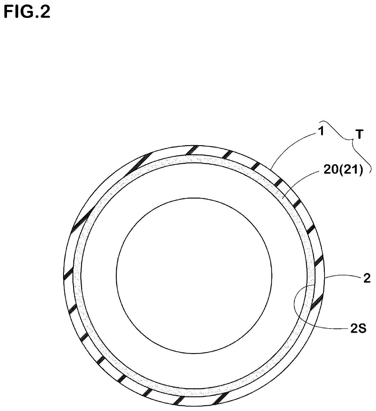
[0033]As shown in FIG. 1, a pneumatic tire with a noise damper (T) of the present embodiment is provided with a pneumatic tire 1 and a noise damper 20 made of a porous resin foam and arranged on a tread inner surface (2S) thereof.

[0034]The pneumatic tire 1 is a tubeless tire and can be of a well-known structure. The pneumatic tire 1 of the present embodiment is provided with a carcass 6 extending between bead cores 5 of bead portions 4 and a tread portion 2 via sidewall portions 3, and a belt layer 7 arranged outside the carcass 6 in a tire radial direction and inside the tread portion 2.

[0035]The carcass 6 is formed by at least one (one in this embodiment) carcass ply 6A having carcass cords arranged at an angle of 75 degrees or more and 90 degrees or less with respect to the tire circumferential direction, for example. In each of the bead portions 4, a bead apex rubber 8 extending radially outward from a ...


PUM

PropertyMeasurementUnit
densityaaaaaaaaaa
densityaaaaaaaaaa
heightaaaaaaaaaa

Abstract

A pneumatic tire with a noise damper has a noise damper made of porous resin foam and arranged on a tread inner surface. The noise damper is formed by a single annular body extending continuously in a tire circumferential direction. The noise damper has a core density in a range of from 35 to 65 kg / m3 and an overall density in a range of from 50 to 105 kg / m3. A maximum height of the noise damper from the tread inner surface is in a range of from 12 to 30 mm.

Description

TECHNICAL FIELD[0001]The present invention relates to a pneumatic tire with a noise damper having improved road noise reduction effect, and a method of manufacturing the same.BACKGROUND ART[0002]The following Patent Documents 1 and 2 have proposed a pneumatic tire and a method of manufacturing the pneumatic tire in which a continuous ribbon-shaped noise damper spirally wound in a tire circumferential direction is formed directly on an inner surface of the tire by applying a liquid compound containing a blowing agent to the inner surface of the tire.[0003]In this proposed manufacturing method, work efficiency can be significantly improved as compared with the case where a ribbon-shaped sponge body which has been foam-molded in advance is attached to the inner surface of a tire by using, for example, a double-sided adhesive tape.[0004]Further, in the tire, since a continuous groove is formed between the wound portions of the spiral noise damper, heat dissipation is improved, therefore...

Claims


Application Information

Patent Timeline
Patent Type & Authority Applications(United States)
IPC IPC(8): B60C19/00B29D30/00
CPCB60C19/002B29D30/0061B60C19/12B60C1/00
Inventor YUKAWA, NAOKIMATSUNAMI, SHOSATO, TAKUYAKINAMI, SAEKOSADO, SHINICHIROIDO, HIROAKIURANO, ATSUSHI
Owner SUMITOMO RUBBER IND LTD
Learn More