
Method of calibrating a radiotherapy system

a radiotherapy system and calibration method technology, applied in the direction of radiation therapy, calibration apparatus, instruments, etc., can solve the problems of inaccurate knowledge of the location of the diaphragm, inability to provide a solution to the alignment of the beam measurement device with the radiation head, etc., to eliminate the errors associated with backlash, wide cross-sectional area, and wide surface area

Active Publication Date: 2012-12-13
ELEKTA AB
View PDF2 Cites 1 Cited by
  • Summary
  • Abstract
  • Description
  • Claims
  • Application Information

AI Technical Summary

Benefits of technology

[0006]Modern beam measurement devices can provide a wider surface area, to the point where scanning of the device across the beam is no longer necessary; eliminating the errors associated with backlash. For example, an ion chamber array (such as that described by U.S. Pat. No. 6,125,335) can be used to provide a detecting device with a wide cross-sectional area. This is a flat bed of multiple ion chambers arranged along the major axes that would previously have been scanned. As the array has no moving parts there are no backlash issues as with the scanning ion chamber.
[0007]This does not provide a solution to the alignment of the beam measurement device with the radiation head, however. As we now have a repeatable method of measuring the beam without the mechanical variation of a scanning ion chamber being an issue, it would be better if the beam measurement device (i.e. the ion chamber array) could be located in the same position every time, relative to the head of the gantry (not relative to the beam—this is what we want to use to align the beam). This would give a better consistency of machine set up.
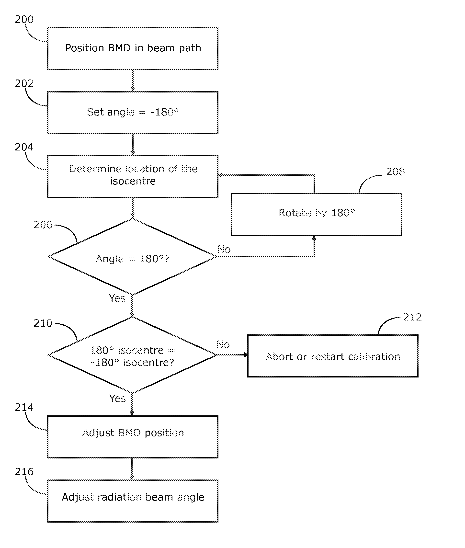
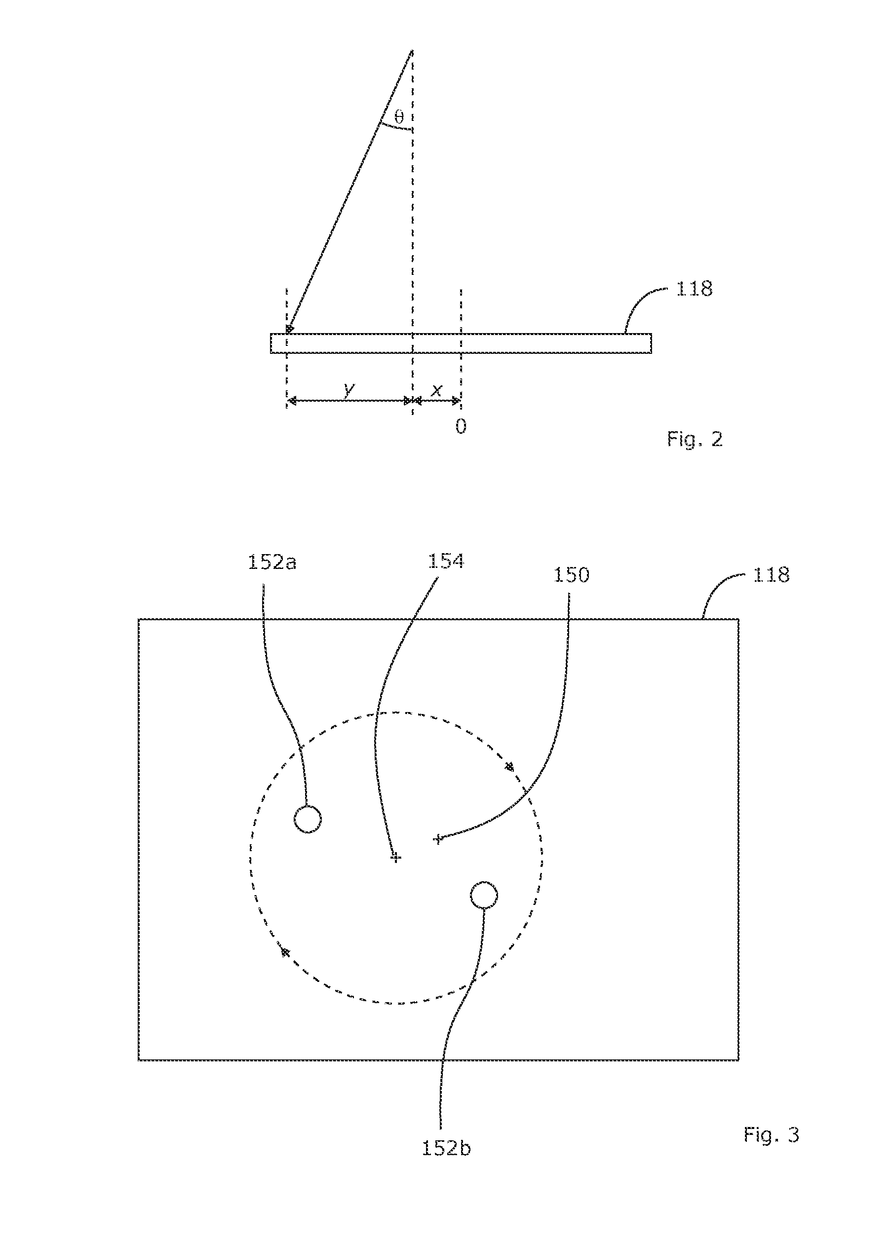
[0009]The present invention provides a method of calibrating a radiotherapy apparatus, in which a beam measurement device is accurately located to coincide with the centre of a desired beam axis. The centre of the radiation beam is determined, the radiation head (to which the beam measurement device is coupled) rotated by 180°, and the centre of the radiation beam determined again. The beam measurement device may then be repositioned so that it is aligned with the midpoint of the relative displacement of the two centres.

Problems solved by technology

This does not provide a solution to the alignment of the beam measurement device with the radiation head, however.
However, a diaphragm edge is required to flatten the beam, and at such an early stage of calibration the diaphragm location may not be accurately known.

Method used


Image

  • Method of calibrating a radiotherapy system
  • Method of calibrating a radiotherapy system
  • Method of calibrating a radiotherapy system

Examples


Embodiment Construction

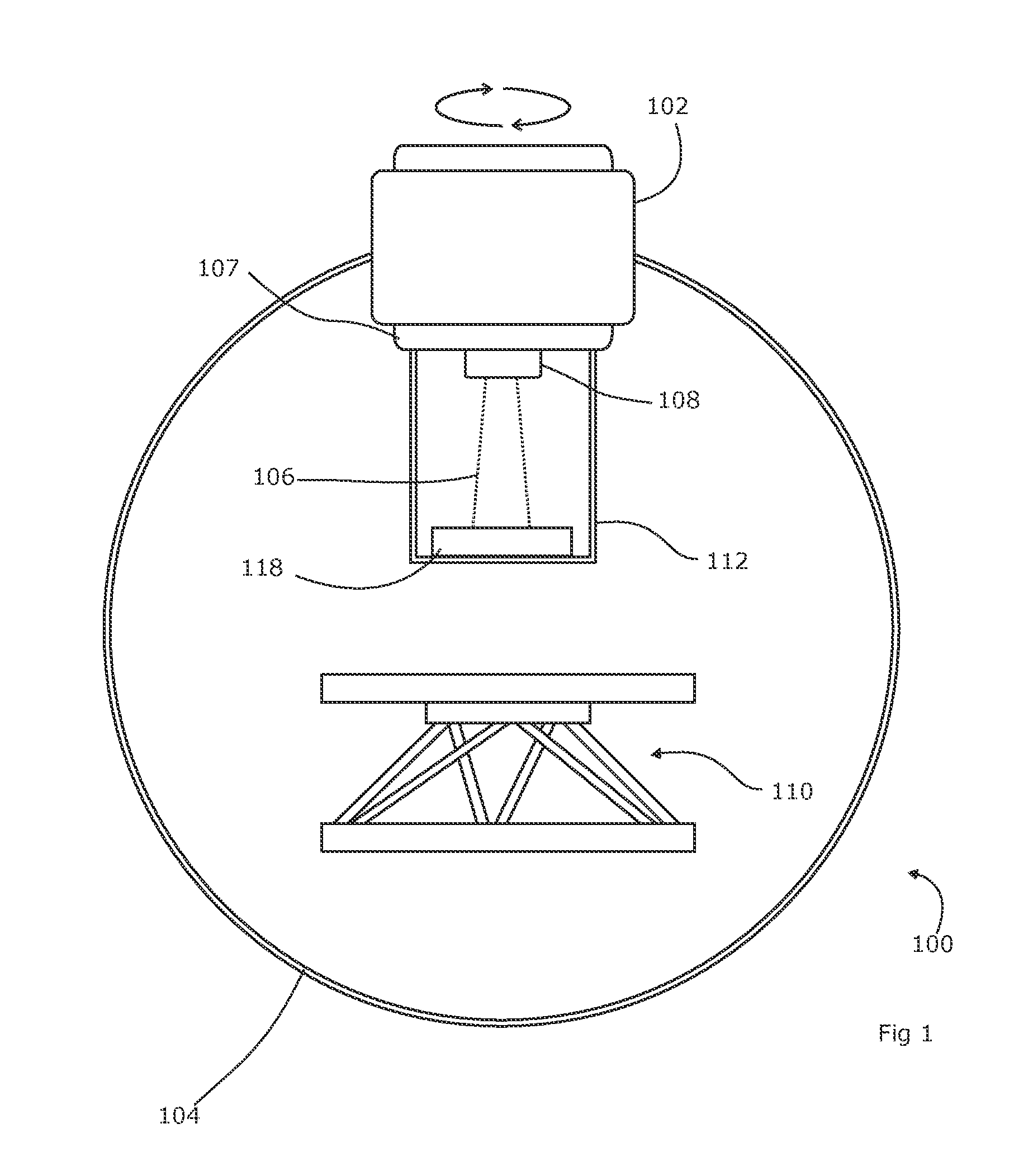
[0022]FIG. 1 shows one example of a radiotherapy apparatus 100 such as may be calibrated by methods according to embodiments of the present invention.

[0023]The radiotherapy system comprises a source of ionizing radiation 102, mounted on a gantry 104 and arranged to produce a beam of radiation 106. A support apparatus 110 is provided to support a patient during treatment, and as such is positioned to intersect the radiation beam 106. Depending on the form of treatment provided, the gantry 104 may be able to rotate so as to direction radiation towards the target from multiple directions. However, the method according to embodiments of the present invention does not rely upon such rotation, and therefore the present invention is applicable to radiotherapy systems where the radiation head is in a fixed position relative to the patient. What is required is that the radiation head 102 is able to rotate about an axis which is approximately coincident with the axis of the radiation beam (se...


PUM


Abstract

The present invention provides a method of calibrating a radiotherapy apparatus, in which a beam measurement device is accurately located with respect to the radiation beam centre. The method comprises acquiring the centre of the radiation beam at two angles of rotation, separated by 180°, and aligning a beam measurement device with the midpoint of the respective centres.

Description

FIELD OF THE INVENTION[0001]The present invention relates to a method of calibrating a radiotherapy system.BACKGROUND ART[0002]Radiotherapy is the use of highly ionizing radiation to damage or kill diseased (e.g. cancerous) cells in a patient. In one form of radiotherapy, a linear accelerator is employed to accelerate charged particles either towards the patient (in which case the charged particles themselves act as the therapeutic radiation) or towards an x-ray target (in which case the x-rays so generated have the therapeutic effect). The radiation is highly damaging to all cells in its path (i.e. both healthy and unhealthy), so the shape and direction of the radiation must be carefully controlled to conform to precise standards.[0003]As part of this process, the radiation is usually first collimated into a beam (cone- and fan-shaped beams are well known in the art, but other shapes are possible) by so-called “primary” collimators, and then further collimated to conform to the sha...

Claims


Application Information

Patent Timeline
Patent Type & Authority Applications(United States)
IPC IPC(8): G01D18/00
CPCA61N5/1075
Inventor THWAITE, GRAHAM
Owner ELEKTA AB
Learn More