
Condenser
a condenser and condenser technology, applied in the field of condensers, can solve problems such as the rupture of the heat exchange tube, and achieve the effects of enhancing heat exchange performance, reducing frictional loss and local resistance, and increasing the condensing pressure of the refrigerant gas
- Summary
- Abstract
- Description
- Claims
- Application Information
AI Technical Summary
Benefits of technology
Problems solved by technology
Method used
Image

Examples
Embodiment Construction
[0031]Various particular embodiments of the present invention are described below with reference to the accompanying drawings, which form part of this Description. It should be understood that although terms indicating direction, such as “front”, “rear”, “up”, “down”, “left” and “right”, etc. are used in the present invention to describe various demonstrative structural parts and elements of the present invention in a directional or orientational manner, these terms are used here purely in order to facilitate explanation, and are determined on the basis of demonstrative orientations shown in the drawings. Since the embodiments disclosed in the present invention may be arranged in accordance with different directions, these terms indicating direction are purely illustrative, and should not be regarded as limiting. In the drawings below, identical components use identical reference labels, and similar components use similar reference labels.
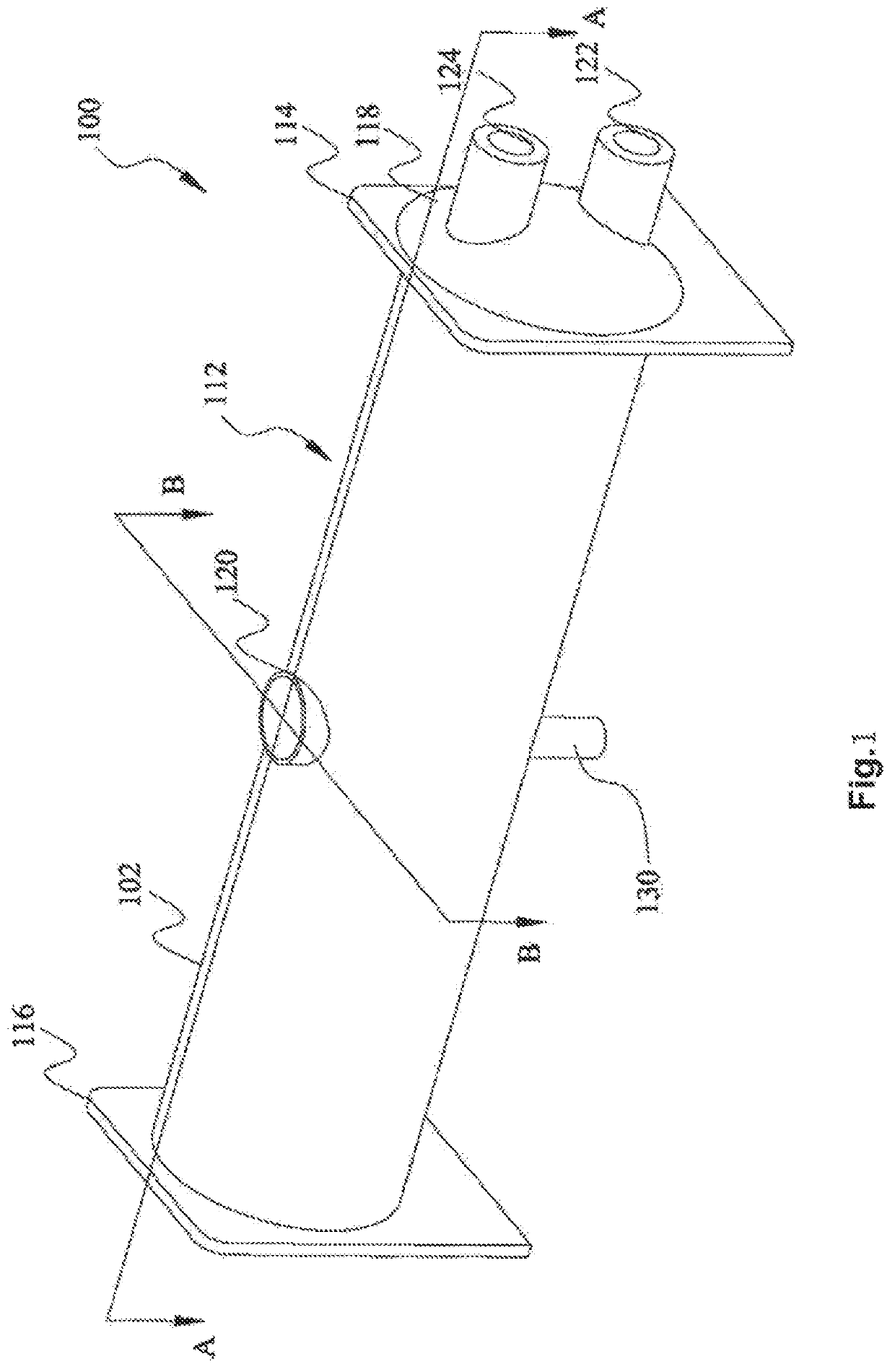
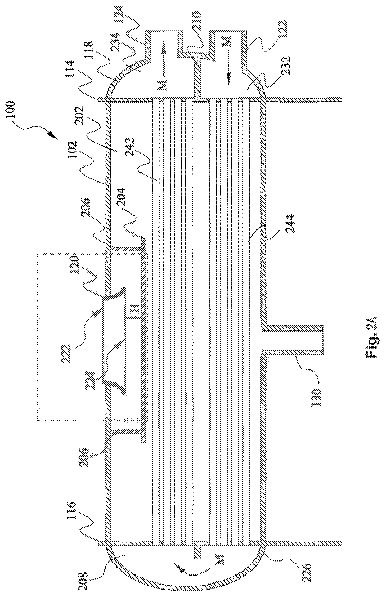
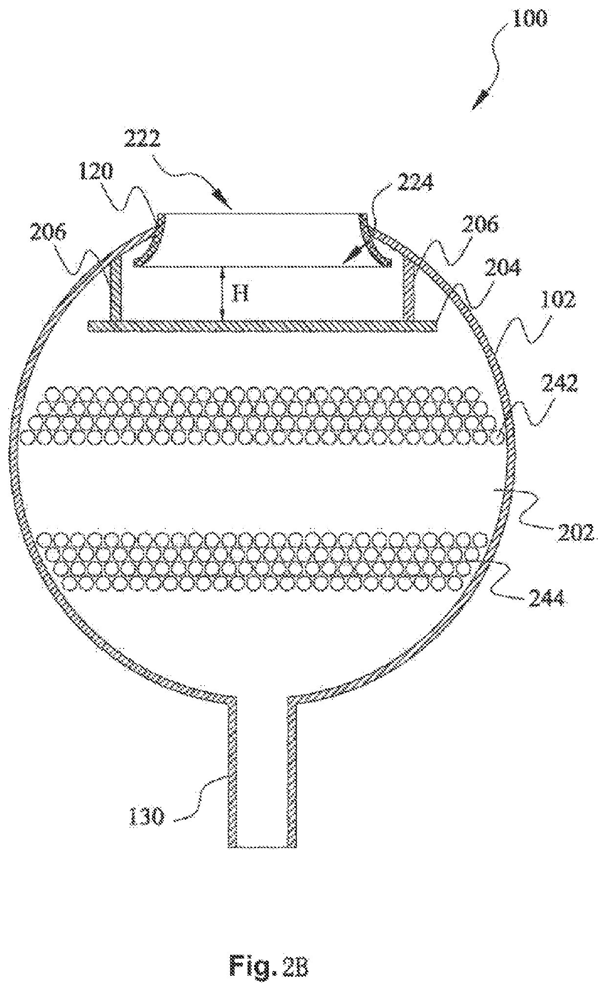
[0032]FIG. 1 is a three-dimensional drawing ...
PUM
 Abstract
Description
Claims
Application Information