Eureka AIR delivers breakthrough ideas for toughest innovation challenges, trusted by R&D personnel around the world.

An arrangement for a coaxial cable connector

Active Publication Date: 2021-10-07
TELESTE
View PDF0 Cites 0 Cited by
  • Summary
  • Abstract
  • Description
  • Claims
  • Application Information

AI Technical Summary

Benefits of technology

The invention is a connector for joining a coaxial cable to a connector. The connector has a ferrule that makes contact with the cable's metal braid layer, and an insulating layer that is stripped away to make contact with the ferrule. A collar is positioned around the ferrule and has a similar outer diameter as the cable's outer insulating layer. A silicone sleeve is placed between the collar and the cable's braiding, providing a pressure force to the metal braid layer. The collar has a front edge with an inward edge. The invention provides a more reliable and reliable connection between coaxial cables and connectors.

Problems solved by technology

Any degradation in overall contact resistance will result in increasing the transfer impedance and will degrade the screening effectiveness.
It has turned out that while a cable interconnect assembly using such connectors may meet the Class A++ CENELEC standard requirements when manufactured, the coupling transfer function of practically all assemblies has degraded significantly after having been installed in a CATV network some time.
However, while being very effective in terms of preventing the damages of the metal braid layer and oxidising of the aluminium braiding, the installation of the silicone sleeve around the metal braid layer after removing an outer plastic jacket has faced some challenges.
However, removing the outer jacket of cable upon installation reduces the diameter of the cable such that achieving sufficient pressure with a pre-installed sleeve may become difficult.

Method used


Image

  • An arrangement for a coaxial cable connector
  • An arrangement for a coaxial cable connector
  • An arrangement for a coaxial cable connector

Examples


Embodiment Construction

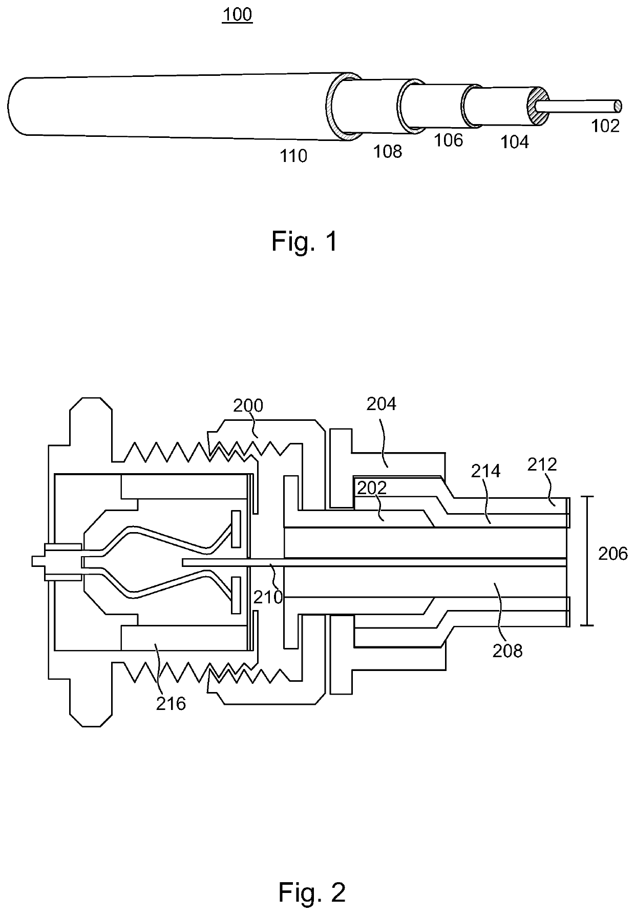
[0022]FIG. 1 shows an example of the structure of a coaxial cable. The cable 100 comprises an inner (or centre) conductor 102 for conducting electrical signals. The inner conductor 102 is typically made of copper or copper plated steel. The inner conductor 102 is surrounded by an insulating layer 104 forming a dielectric insulator around the conductor 102. The insulator surrounding the inner conductor may be solid plastic, such as polyethylene (PE) or Teflon (PTFE), a foam plastic, or air with spacers supporting the inner conductor.

[0023]The insulating layer 104 is surrounded by a thin metallic foil 106 typically made of aluminium. This is further surrounded by a woven metallic braid 108. FIG. 1 shows only one braid layer 108, but there may be two (inner and outer) layers of braid, or even more braid layers. Braiding is typically made of unalloyed aluminium, copper or tinned copper, depending on the intended field of use of the coaxial cable. For example, coaxial cables used in vari...


PUM


Abstract

A connector suitable for being mounted on a coaxial cable comprising at least one metal braid layer surrounding inner parts of the cable and an outer insulating layer surrounding said at least one metal braid layer and a silicone sleeve arranged around the outer insulating layer wherein the connector comprises a ferrule to be arranged in electrical contact with said at least one metal braid layer, wherein said outer insulating layer of the cable is arranged to be stripped away for the length of said electrical contact, a base arranged cylindrically around said ferrule, and a collar arranged at least partially within said base and comprising a body configurable around the ferrule; wherein the body of the collar has a first outer diameter substantially the same as the diameter of the outer insulating layer of the coaxial cable; and the silicone sleeve is arranged, upon mounting the coaxial cable to the connector, between the base and the body of the collar for applying a pressure force to said at least one metal braid layer of the coaxial cable guided to an outer surface of the collar.

Description

FIELD OF THE INVENTION[0001]The present invention relates to television network installations and more particularly to an arrangement for a coaxial cable connector.BACKGROUND OF THE INVENTION[0002]F type connectors, specified in the standard IEC 60169-24, have been used for decades for terrestrial, cable, and satellite TV installations. The male F connector body is typically crimped or compressed onto the exposed outer braid of the coaxial cable. Female F Type connectors have an external thread to which male connectors having a matching internally threaded connecting ring are connected by screwing. In various TV installations, it is vital that the metal-to-metal contact resistance between the connector and the cable braiding is optimised and maintained over time for good contact resistance. Any degradation in overall contact resistance will result in increasing the transfer impedance and will degrade the screening effectiveness.[0003]It has turned out that while a cable interconnect...

Claims


Application Information

Patent Timeline
IPC IPC(8): H01R9/05H01R4/70
CPCH01R9/0524H01R9/0521H01R4/70
Inventor GRIBBY, STEVE
Owner TELESTE
Why Eureka
Eureka Blog
Learn More