Devices, Systems, And Methods For Corn Headers

Pending Publication Date: 2021-10-14
LEADER TECH
View PDF0 Cites 0 Cited by
  • Summary
  • Abstract
  • Description
  • Claims
  • Application Information

AI Technical Summary

Benefits of technology

[0014]Example 8 relates to a system for minimizing yield loss comprising a row unit on a corn header. The row unit comprising a pair of stripper plates defining a stripper plate gap on the row unit and at least one sensing member attached to the row unit, the

Problems solved by technology

These loose kernels may then fall to the ground and become unwanted header loss—lost yield.
This harvesting error often go

Method used


Image

  • Devices, Systems, And Methods For Corn Headers
  • Devices, Systems, And Methods For Corn Headers
  • Devices, Systems, And Methods For Corn Headers

Examples


Embodiment Construction

[0046]Discussed herein are various devices, systems, and methods for increasing yield by minimizing loss due to harvester error. In various implementations, a system is provided for emitting warnings / alarms when the corn head is not at an optimal height, such that yield is not lost due to shelling / threshing of ears by the stripper plates and / or stalk rolls.

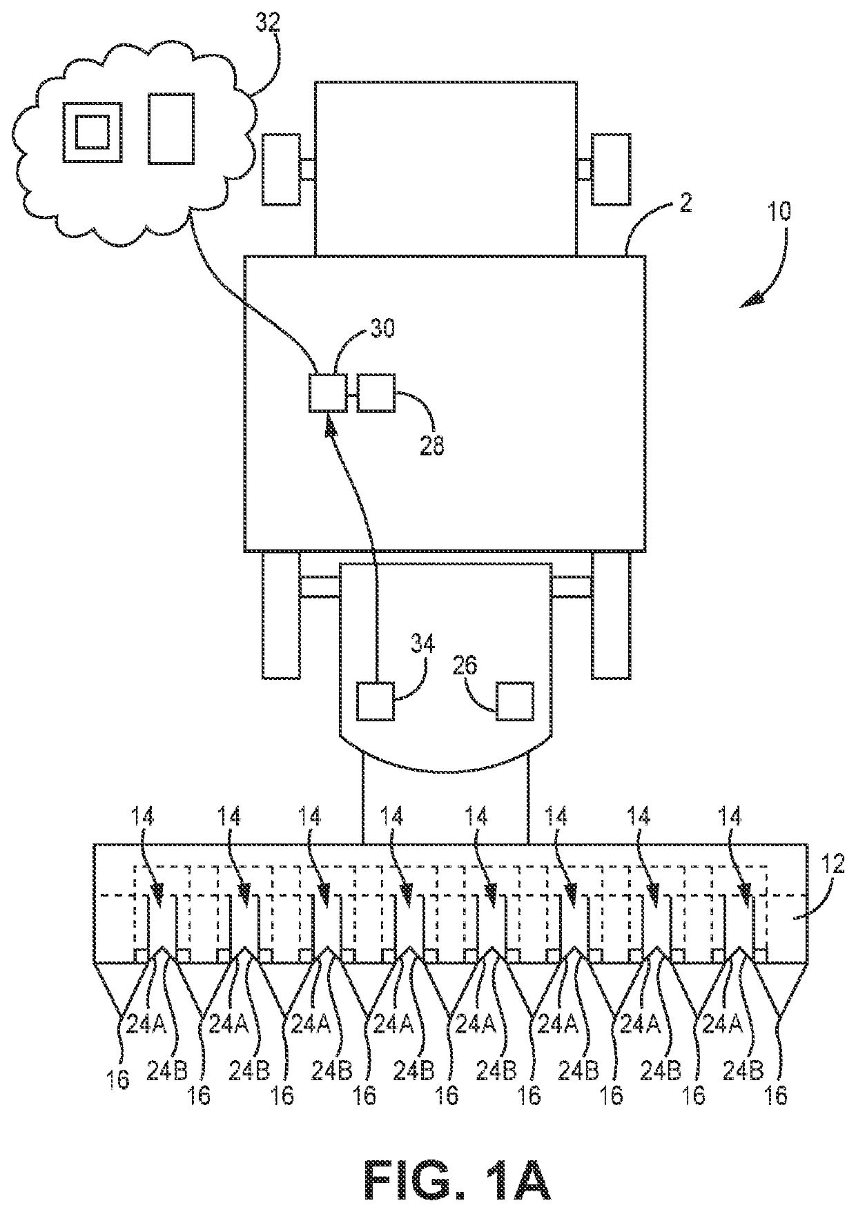
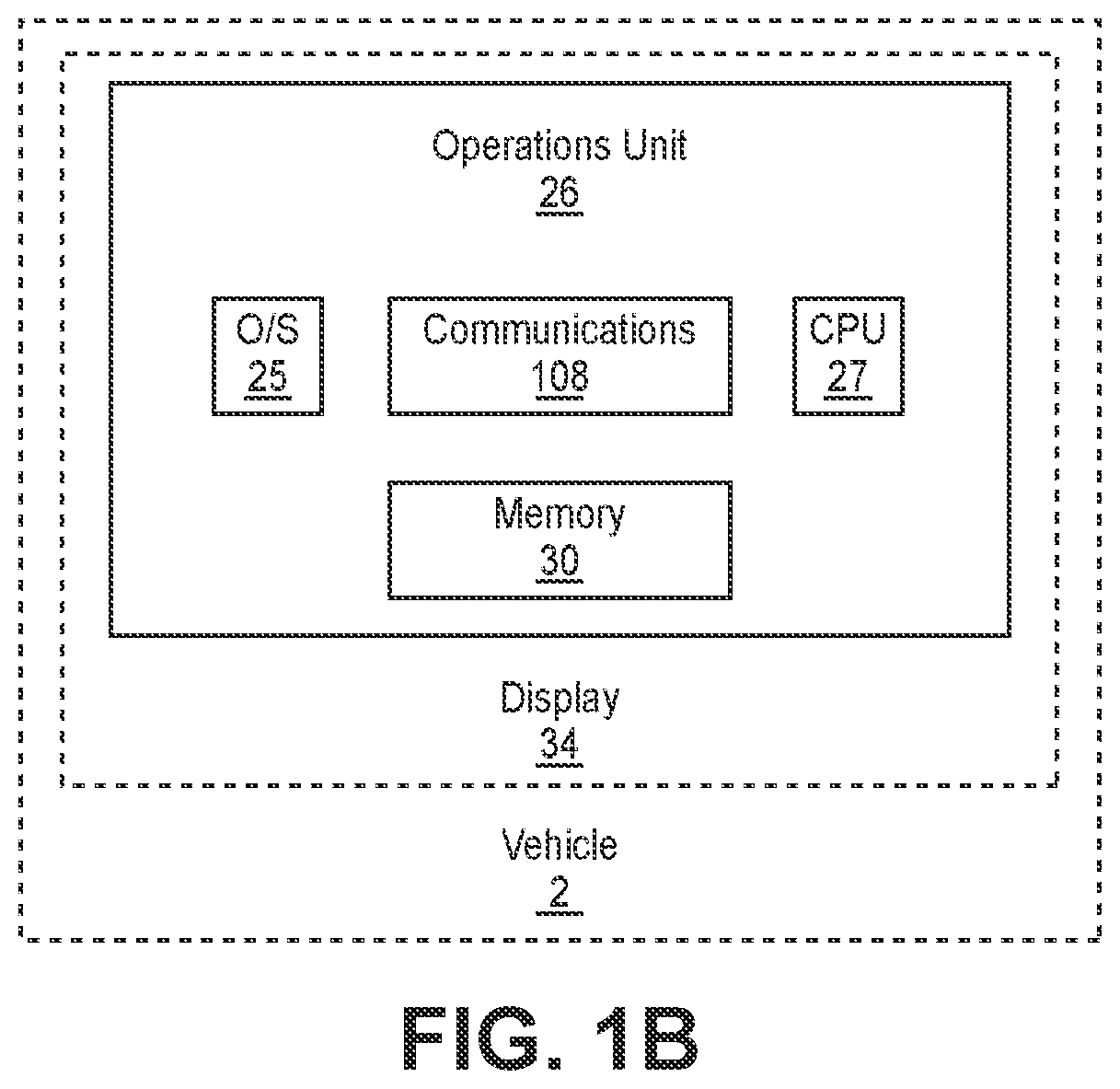
[0047]Turning now to FIGS. 1A-1B, it is readily appreciated that the disclosed header warning system 10 may be used in connection with any known harvester 2. A harvester 2 having a header 12 and header warning system 10 may be configured to harvest row crops. In various implementations such as that of FIGS. 1A-1B, a harvester 2 is configured to harvest crops through the row units 14 disposed on the corn header 12, as would be readily appreciated.

[0048]Various harvester 2 configurations are possible and known in the art. In the implementation of FIGS. 1A-1B the harvester 2 includes a header 12 including a plurality of row units 14 ...


PUM


Abstract

Disclosed herein are various devices, systems, and methods for use in agricultural, particularly for use in harvesting agricultural crop such as corn. Various implementations relate to devices, systems, and methods for increasing yield by emitting warnings when the corn head to not at the proper height.

Description

CROSS-REFERENCE TO RELATED APPLICATION(S)[0001]This application claims the benefit under 35 U.S.C. § 119(e) to U.S. Provisional Application 63 / 006,774, filed Apr. 8, 2020, and entitled Agricultural Devices, Systems, and Methods, which is hereby incorporated herein by reference in its entirety for all purposes.TECHNICAL FIELD[0002]The disclosure relates to various devices, systems, and methods for use in agricultural applications, particularly for use during agricultural harvest and in conjunction with corn headers.BACKGROUND[0003]It is appreciated by those of skill in the art that when a corn ear enters a harvester row unit at or slightly below the stripper plate, the stalk rolls may thresh or shell off kernels from the ear. These loose kernels may then fall to the ground and become unwanted header loss—lost yield. This harvesting error often goes undetected because it is typically only a periodic problem and in most circumstances is difficult to see from the cab.[0004]There is a ne...

Claims


Application Information

Patent Timeline
IPC IPC(8): A01D45/02A01D41/127A01B63/00G08B21/18
CPCA01D45/021A01D41/127G08B3/00A01D45/028G08B21/182A01B63/008G01B5/10G01B5/04G01B5/0035A01D41/1273A01D41/141G08B5/00G01B21/06G01D21/00
Inventor ZIELKE, ROGER
Owner LEADER TECH
Why Eureka
Try Eureka