
Nozzle device applied to high-pressure cleaning machine and handheld high-pressure cleaning machine

a high-pressure cleaning and nozzle device technology, applied in the direction of cleaning process and equipment, cleaning using liquids, chemistry apparatus and processes, etc., can solve the problems of difficult gas discharge of the pump, long time for self-suction, and difficulty in releasing air and water mixture, etc., to achieve the effect of quickly eliminating pressure anomalies during us

Pending Publication Date: 2021-10-14
POSITEC POWER TOOLS (SUZHOU) CO LTD
View PDF0 Cites 1 Cited by
  • Summary
  • Abstract
  • Description
  • Claims
  • Application Information

AI Technical Summary

Benefits of technology

This patent describes a nozzle device for a high-pressure cleaning machine that can quickly fix pressure issues. The device has an exhaust valve that can open to release vacuum pressure and close to prevent water from coming out. This valve helps to quickly stabilize the pressure and ensure that the machine operates efficiently.

Problems solved by technology

It is difficult to discharge the mixture of air and water.
In addition, gas accumulates at a water outlet end to cause an increase in a pressure, it further becomes difficult for the gas in the pump to discharge.
Consequently, self-suction takes a long time, or even a normal pressure for normal water spraying may fail to be restored.

Method used


Image

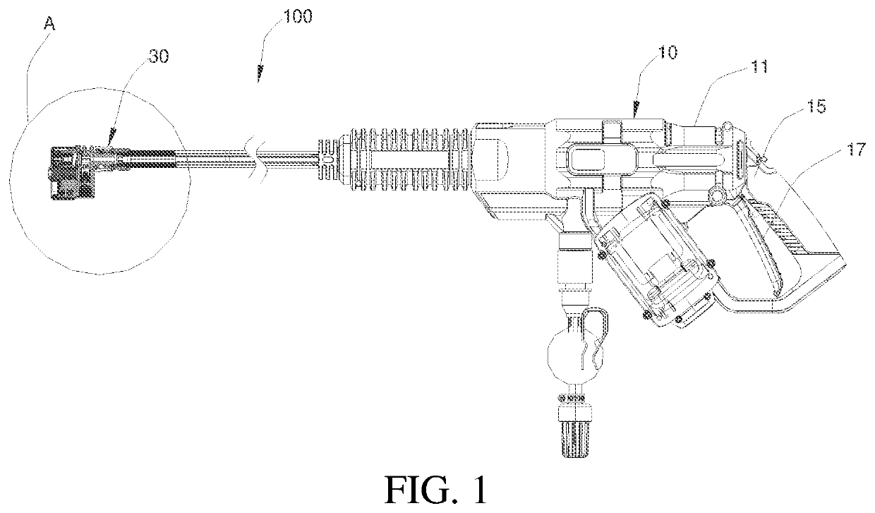
  • Nozzle device applied to high-pressure cleaning machine and handheld high-pressure cleaning machine
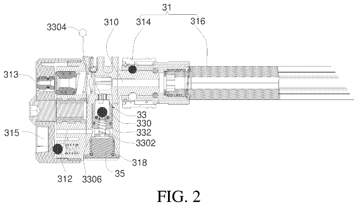
  • Nozzle device applied to high-pressure cleaning machine and handheld high-pressure cleaning machine
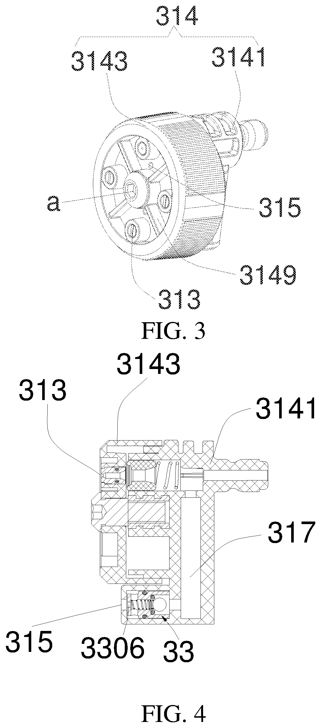
  • Nozzle device applied to high-pressure cleaning machine and handheld high-pressure cleaning machine

Examples


first embodiment

[0127]Referring to FIG. 8, in a first embodiment, the first cavity 3311 and the second cavity 3312 are both round holes with constant inner diameters in the axial direction. The inner diameter of the first cavity 3311 is greater than the inner diameter of the second cavity 3312, so that a step is formed between the first cavity 3311 and the second cavity 3312. The exhaust valve 33 includes a seal ring 334. The seal ring 334 is a circular ring supported on the step. The core body 3321 is a steel ball matching the seal ring 334 in shape. It may be understood that, in some other embodiments, the shape of the seal ring 334 and the shape of the core body 3321 may be determined as required, provided that the seal ring and the core body can seal the end at which the first cavity 3311 connects with the second cavity 3312 when the valve core 332 is at the closed position relative to the valve seat 330. This is not limited herein.

[0128]When the handheld high-pressure cleaning machine 100 is s...

fourth embodiment

[0136]Referring to FIG. 12 and FIG. 13, in a fourth embodiment, the valve core 332 includes the core body 3321, the reset member 3323, and a valve stem 3325 connected to the core body 3321. The core body 3321 is slidably accommodated in the first cavity 3311 in a direction toward or away from the second cavity 3312. The valve stem 3325 movably passes through the second cavity 3312 in an axial direction of the valve stem and protrudes from the main body 31. The reset member 3323 is sleeved in the valve stem 3325 and abuts between the valve seat 330 and the valve stem 3325, to provide the valve core 332 with a restoring force from the closed position to the open position. That is, in this embodiment, the exposed valve stem 3325 is used to manually control opening or closing of the core body 3321 relative to the valve cavity 3302.

[0137]In the foregoing first to fourth embodiments, a gap is provided between an outer contour of the air inlet hole 3304 and an outer contour of a cross sect...


PUM


Abstract

A nozzle device applied to a high-pressure cleaning machine is provided, including: a nozzle, including a nozzle casing, where a water outlet channel is provided in the nozzle casing, and a front end of the nozzle casing is provided with at least one liquid discharge port connecting with the water outlet channel; and an exhaust valve, connected to the nozzle casing, and including: a valve seat, provided with a valve cavity; and a valve core, movably arranged in the valve cavity; where the valve seat is provided with an air inlet hole and an air outlet hole, the water outlet channel and a main exhaust passage are arranged in parallel in the nozzle casing, and the valve core is movable relative to the valve cavity to a closed position for blocking the main exhaust passage and an open position for opening the main exhaust passage. In the nozzle device applied to a high-pressure cleaning machine and a handheld high-pressure cleaning machine that are provided in this application, the exhaust valve is provided, and the exhaust valve implements an exhaust function at the open position, and implements a water outlet function at the closed position, thereby implementing self-suction and ensuring that a pressure anomaly is quickly eliminated within a short time during use, to meet a use requirement.

Description

CROSS REFERENCE[0001]This application is the National Stage filing under 35 U.S.C. 371 of International Application No. PCT / CN2019 / 102427, filed on Aug. 26, 2019, which claims the benefit of earlier filing date and right of priority to Chinese Application No. 201810989402.7, filed Aug. 28, 2018, the contents of which are all hereby incorporated by reference herein in their entirety.BACKGROUNDTechnical Field[0002]The present invention relates to the field of high-pressure cleaning, and in particular, to a nozzle device applied to a high-pressure cleaning machine and a handheld high-pressure cleaning machineRelated Art[0003]High-pressure cleaning machines are widely used in daily life to clean yards, corridors, outdoor tables and chairs, windows, glass, stairs, and cars. A high-pressure cleaning machine is usually provided with a main unit inside which a motor and a pump driven by the motor are disposed, and further includes a spray gun connected to the water pump. In an initial start...

Claims


Application Information

Patent Timeline
IPC IPC(8): B05B12/08B08B3/02B05B9/01B05B9/04
CPCB05B12/087B08B3/026B08B2203/027B05B9/04B08B2203/0211B05B9/01B05B9/0403B08B3/028B05B9/0426B05B1/1654
Inventor QIAO, YONGWANG, QIBINCHENG, YAJIE
Owner POSITEC POWER TOOLS (SUZHOU) CO LTD
Learn More