Image forming method and image forming system

a technology of image forming and forming method, which is applied in the field of image forming method and image forming system, can solve the problems of increasing the amount of scratches and wear on the photoreceptor, increasing the cost of photoreceptors, so as to achieve both cleaning performance and memory performance, and stable supply of high-quality images. , the effect of high durability

Active Publication Date: 2021-10-14
KONICA MINOLTA INC
View PDF0 Cites 0 Cited by
  • Summary
  • Abstract
  • Description
  • Claims
  • Application Information

AI Technical Summary

Benefits of technology

[0011]The present invention has been made in view of the above problems and circumstances. An object of the present invention is to provide an image forming method and an image forming system that may stably supply high-quality images even in long-term use by allowing an electrophotographic photoreceptor to maintain high durability while achieving both cleaning performance and memory performance in an image forming method using a toner for electrostatic charge image development and an electrophotographic photoreceptor.
[0012]In order to solve the above-mentioned problems, the present inventors have found the following in the process of examining the causes of the above-mentioned problems. That is, in an image forming method using the toner for electrostatic image development and the electrophotographic photoreceptor, since the electrophotographic photoreceptor has a photosensitive layer, the photosensitive layer contains a triphenylamine derivative having a specific structure as a charge transport material, and the toner for electrostatic image development contains at least titanic acid compound particles as an external additive, the photoreceptor may maintain high durability while maintaining both cleaning performance and memory performance. Thus, it has been found that an image forming method and an image forming system capable of stably supplying high-quality images even in long-term use may be provided, and the present invention has been achieved. In other words, the problem relating to the present invention is solved by the following means.
[0017]In the image forming method of the present invention, the used photoreceptor contains a charge transport material having the structure represented by the above Formula (1) (hereinafter, also referred to as a charge transport material (1)) in the photosensitive layer of the photoreceptor, whereby the memory performance is ensured. Further, since the used toner contains titanic acid compound particles as an external additive, an image forming method in which the charging amount of the toner is controlled and the cleaning performance is excellent may be provided.
[0018]The amount of charging of the toner may be controlled by holding the external additive in the toner. In the present invention, as the external additive, titanic acid compound particles are used to control the amount of charge of the toner to be small, thereby weakening the adhesion of the toner to the photoreceptor and ensuring the wiping performance at the time of cleaning. As a result, the direct damage to the photoreceptor is reduced, and the occurrence of filming due to the decrease of the adhering force on the photoreceptor is suppressed, and the effect of preventing white spots in the halftone image is obtained as the image quality.
[0019]Note that the above skeleton (skeleton in which a benzene ring is bonded to 1 of phenyl groups of triphenylamine) possessed by the charge transport material (1) is a structure having transparency to light rays while sufficiently exhibiting memory characteristics. When a photopolymerizable resin is used as a binder resin in forming a photosensitive layer, in the skeleton of the charge transport material (1), since the photopolymerization initiator hardly absorbs light rays to be absorbed, curing of the binder resin is hardly inhibited. Therefore, in particular, when the photosensitive layer is composed of a photopolymerizable resin, the effect of using the charge transport material (1) becomes more remarkable.

Problems solved by technology

In particular, due to the increase in the above-described process speed, the load on the photoreceptor increases during cleaning of the toner, resulting in an increase in the amount of scratches and wear on the photoreceptor.
Since the wear of the photoreceptor leads to decrease of the quality of the image, higher durability has become required for the photoreceptor.
It is also known that in the process of cleaning the toner from the photoreceptor, the magnitude of the non-electrostatic adhesion force on the surface of the photoreceptor affects the cleaning performance.
However, although the addition of such a charge transport material has a certain effect on the memory characteristics, the durability tends to decrease.
Specifically, there has been a problem that the photoreceptor is easily worn, cleaning failure of the toner occurs, and streak-like defects occur in the formed image.
The protective layer of the photocurable resin exhibits strength but is inferior in memory characteristics, and the addition of the charge transport material as described above is required to maintain the memory characteristics.
As described above, since the addition of the charge transport material lowers the intensity of the photoreceptor, there is a problem that both of the durability and the memory characteristics cannot be realized.

Method used


Image

  • Image forming method and image forming system
  • Image forming method and image forming system
  • Image forming method and image forming system

Examples


example 1

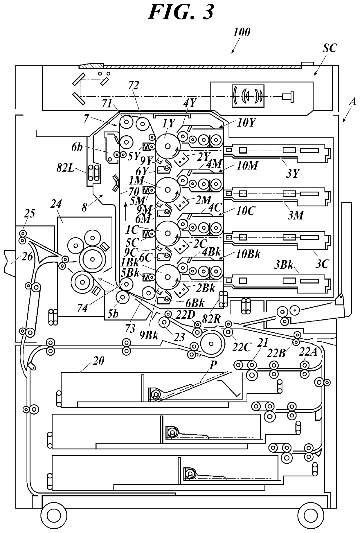
[0398]Using the photoreceptor (1) and the two-component developer (1) prepared above, image formation was performed. As the image forming apparatus, similarly to the image forming apparatus shown in FIG. 3, a tandem-type color image forming apparatus “bizhub C554” (manufactured by Konica Minolta Business Technologies, Inc.) having four sets of image forming units corresponding to toners of four colors of Y, M, C, and Bk was used, and an image forming apparatus (1) in which all four photoreceptors of the image forming apparatus were replaced with photoreceptors (1). The two-component developer (1) was introduced into the developing device of the image forming unit corresponding to the four colors of the image forming apparatus (1).

[0399]Using the image forming apparatus (1) into which the above-mentioned two-component developer (1) was introduced, image formation was conducted for performing the following evaluations (1) to (3), and the cleaning performance, memory performance, and w...

examples 2 to 13

[0416]In Example 1, image formation was performed in the same manner as in Example 1, except that the photoreceptor and the two-component developer were changed as shown in Table IV, and evaluations of cleaning performance, memory performance, and wear resistance of Examples 2 to 13 were performed. The evaluation results are indicated in the table IV. In Table IV, the number of the two-component developer is not listed, but the number of the two-component developer is the same as the number of the toner.

TABLE IVPhotoreceptorTwo-component developerExternal addition amountChargeTitanic acid compound(mass %)Pho-transportSurfaceparticlesWeartore-layerprotective layerExternalresistancecep-ChargeChargeMetalParticleadditionCleaningMemoryEval-tortransporttransportoxideTonerdiameteramountperfor-perfor-αval-ua-No.materialmaterialparticlesNo.No(nm)(mass %)mancemanceuetionRemarksExample 11CTM-1CTM-1Alumina1s1300.5AAAA0.05AAPresent InventionExample 22CTM-30Alumina1s1300.5AAAA0.07AAPresent Invent...


PUM

PropertyMeasurementUnit
number average primary particle diameteraaaaaaaaaa

Abstract

Provided is an image forming method using a toner for developing an electrostatic charge image and an electrophotographic photoreceptor, and containing at least a charging step, an exposing step, a developing step and a transferring step, wherein the electrophotographic photoreceptor has a photosensitive layer, and the photosensitive layer contains a triphenylamine derivative having a specific structure as a charge transport material, and the toner for developing an electrostatic charge image contains at least titanic acid compound particles as an external additive.

Description

CROSS-REFERENCE TO RELATED APPLICATION[0001]The entire disclosure of Japanese Patent Application No. 2020-071752 filed on Apr. 13, 2020 is incorporated herein by reference in its entirety.BACKGROUNDTechnological Field[0002]The present invention relates to an image forming method and an image forming system. More specifically, the present invention relates to an image forming method and an image forming system capable of stably supplying a high-quality image even in long-term use because the photoreceptor can maintain high durability while maintaining both cleaning performance and memory performance.Description of the Related Art[0003]Recently, there has been a demand for an electrophotographic image forming system capable of providing high-quality printed matter at a higher speed in the electrophotographic system in the commercial printing field.[0004]In an electrophotographic image forming system, image formation is performed through a charging step, an exposing step, a developing ...

Claims


Application Information

Patent Timeline
Patent Type & Authority Applications(United States)
IPC IPC(8): G03G9/097G03G5/07G03G15/08G03G9/08
CPCG03G9/09708G03G9/0819G03G15/08G03G5/0764G03G13/013G03G5/14786G03G5/14795G03G5/14704G03G5/14734
Inventor MAEDA, SEISUKE
Owner KONICA MINOLTA INC
Why Eureka
Try Eureka