Fluid control apparatus

a control apparatus and fluid technology, applied in valve housings, process and machine control, instruments, etc., can solve the problems of difficult to reduce the size of the mass flow controller, and achieve the effect of increasing the maximum flow rate and reducing the width of the block

Active Publication Date: 2021-10-14
HORIBA STEC CO LTD
View PDF8 Cites 0 Cited by
  • Summary
  • Abstract
  • Description
  • Claims
  • Application Information

AI Technical Summary

Benefits of technology

[0025]According to the fluid control apparatus, the first outflow channel and the second inflow channel are disposed in the block so as to overlap each other at one position as viewed in the width direction through the block. Accordingly, the first control valve and the second control valve can be arrayed on the block in the longitudinal direction, which enables the width of the block to be reduced while the fluid is able to flow out of each control valve into the confluent channel. Thus, the fluid control apparatus can be formed compactly while increasing the maximum flow rate compared with the known configuration.

Problems solved by technology

In this case, even though the maximum flow rate can be increased, it may be difficult to reduce the size of the mass flow controller.

Method used


Image

  • Fluid control apparatus
  • Fluid control apparatus
  • Fluid control apparatus

Examples


first embodiment

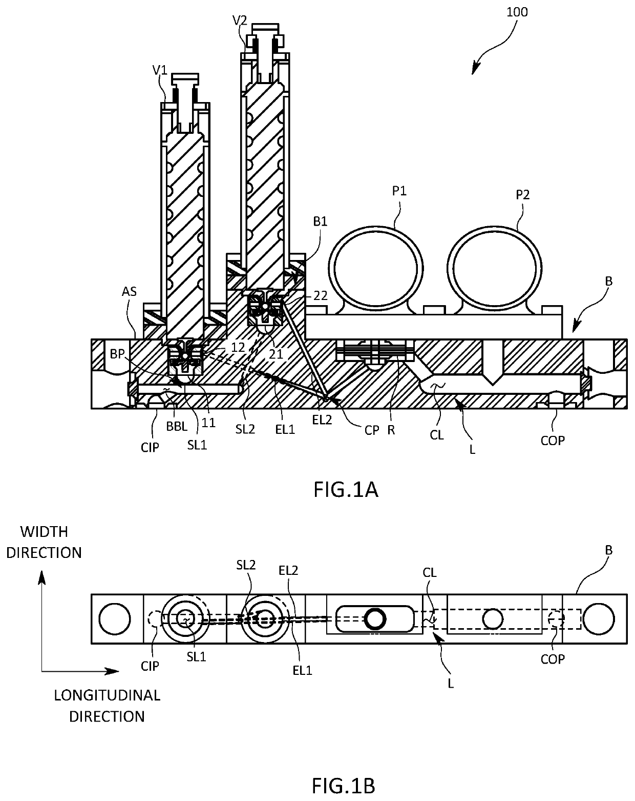
[0034]A fluid control apparatus 100 will be described with reference to FIGS. 1A to 3.

[0035]The fluid control apparatus 100 is used, for example, in a semiconductor manufacturing process, to supply fluids, or specifically various types of gases, to a chamber at a desirable set flow rate. A gas supply system is formed typically by arraying multiple fluid control apparatuses 100 side by side in the width direction.

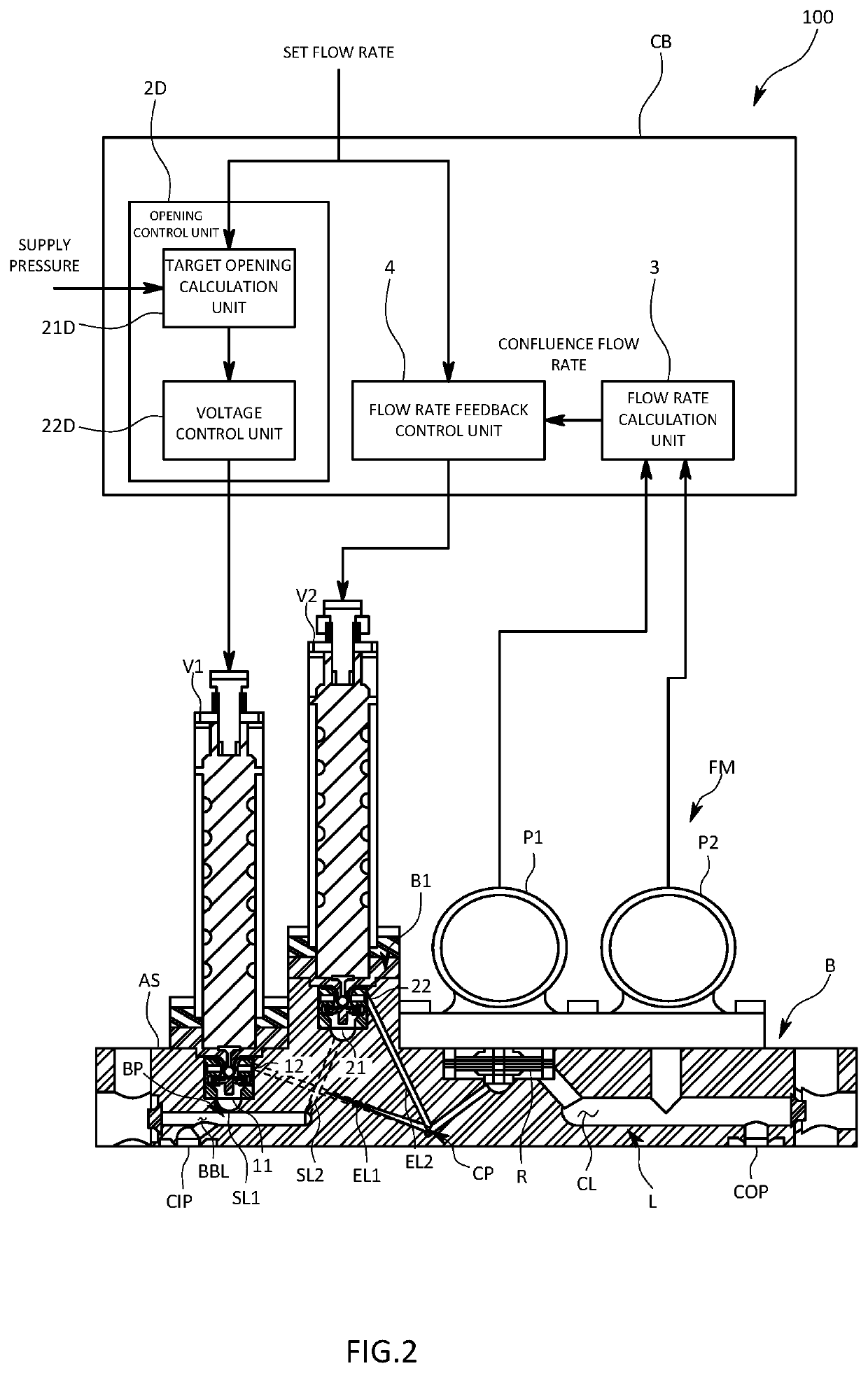
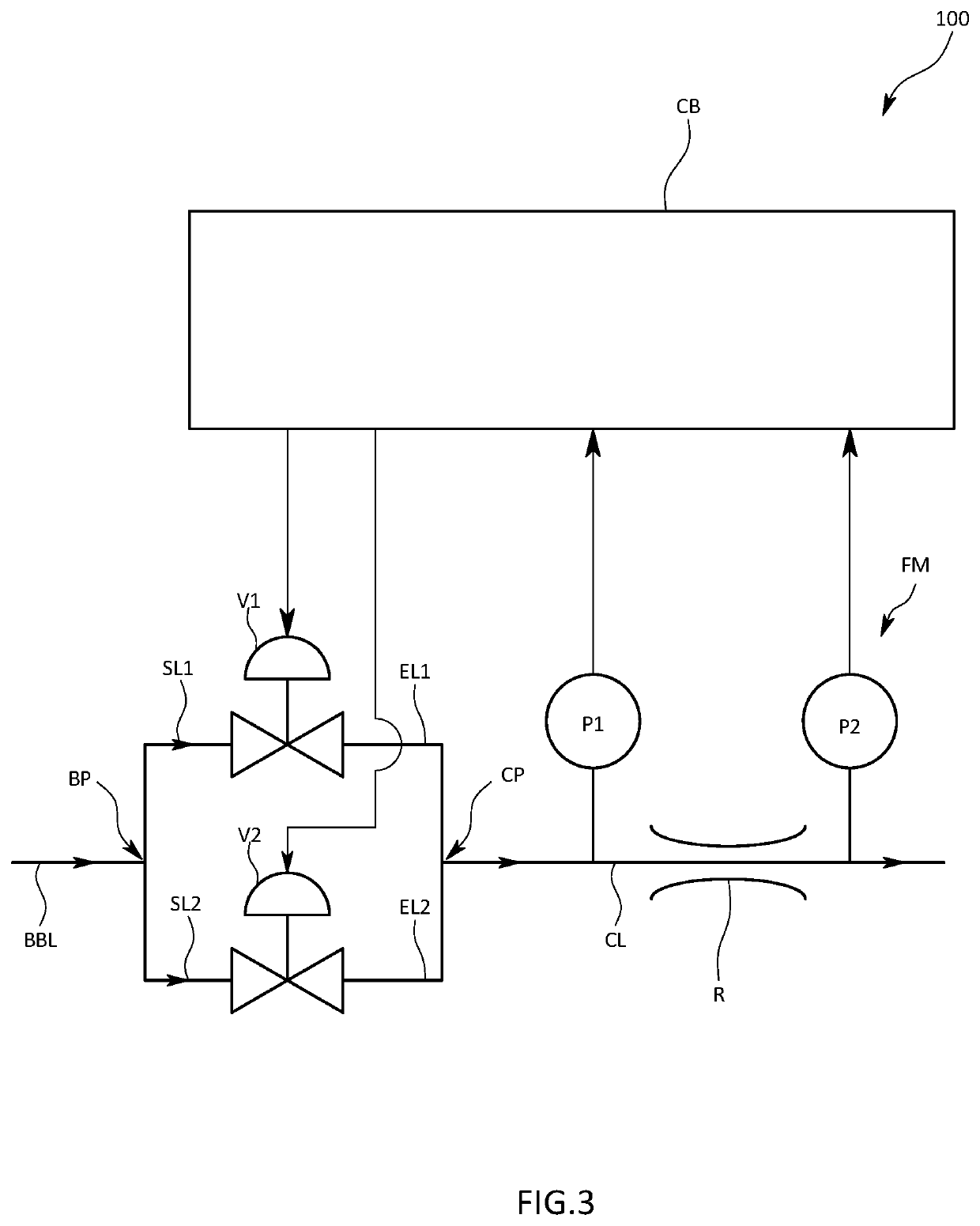
[0036]As illustrated in FIGS. 1A, 1B, and 2, the fluid control apparatus 100, which is elongated in the longitudinal direction, includes a block B, a first control valve V1, a second control valve V2, a flow rate sensor FM, and a fluid controller CB. The block B has an internal flow channel L formed inside through which a gas flows from one end to the other. The first control valve V1 and the second control valve V2 are mounted on the block B. The flow rate sensor FM is a pressure sensing device that measures the flow rate of the confluent gas that has passed through the fi...

second embodiment

[0058]The fluid control apparatus 100 has such a structure that the valve plugs and the valve seats of the first control valve V1 and the second control valve V2 are not inserted in the block B and that the first control valve V1 and the second control valve V2 can be detached individually from the block B.

[0059]More specifically, the first control valve V1 includes a first valve block VB1 in which a valve plug and a valve seat are formed. The bottom surface of the first valve block VB1 is attached to the mounting surface AS of the block B, and the first control valve V1 thereby communicates with the internal flow channel L. The bottom surface of the first valve block VB1 is referred to as a connection surface CS. The first inlet 11 through which the fluid or the gas flows in and the first outlet 12 through which the gas flows out open at the connection surface CS. As illustrated in FIG. 4A, when the connection surface CS is attached to the mounting surface AS, the first inlet 11 i...

third embodiment

[0065]The fluid controller CB of the third embodiment includes a synchronization control unit 5 that controls the first control valve V1 and the second control valve V2 to change the opening in synchronization with each other.

[0066]The synchronization control unit 5 applies the same voltage to the first control valve V1 and to the second control valve V2 so as to decrease the deviation of the confluence flow rate, which is measured by the flow rate sensor FM, from the set flow rate. Here, the first control valve V1 and the second control valve V2 are valves of the same type and size. Accordingly, application of the same voltage causes these valves to open substantially to the same degree. The synchronization control unit 5 is configured to change the voltage applied to each control valve in accordance with the deviation of the measurement results from the set flow rate in such a manner that substantially the same voltage is applied to each control valve at any given time. For exampl...


PUM


Abstract

A fluid control apparatus includes a block elongated in a longitudinal direction and having a predetermined width, an internal flow channel formed inside the block so as to extend in the longitudinal direction, a first control valve mounted on the block, a second control valve mounted on the block at a position downstream of the first control valve. In the fluid control apparatus, the internal flow channel has a first outflow channel connected to a first outlet of the first control valve through which a fluid flows out thereof and also has a second inflow channel connected to a second inlet of the second control valve through which the fluid flows thereinto. In addition, the first outflow channel and the second inflow channel are disposed so as to overlap each other at one point as viewed in the width direction through the block.

Description

BACKGROUND OF THE INVENTIONField of the Invention[0001]The present invention relates to a fluid control apparatus that controls the flow rate and pressure of a fluid, such as a gas.Description of the Related Art[0002]Mass flow controllers are used to control the flow rate of a gas, for example, in a semiconductor manufacturing process. A known mass flow controller includes a block having an internal flow channel formed therein and fluid control instruments, such as pressure sensors and control valves, that are mounted on the block. The block is shaped like a cuboid elongated in the longitudinal direction and having a predetermined width so that multiple mass flow controllers can be arrayed compactly (see International Publication No. 2011 / 040270).[0003]For example, the width of the block is standardized to 10 mm. Multiple fluid control instruments each having substantially the same width as that of the block are arrayed in the longitudinal direction on a longitudinally extending mou...

Claims


Application Information

Patent Timeline
Patent Type & Authority Applications(United States)
IPC IPC(8): G05D7/06F16K37/00
CPCG05D7/0652F16K37/0041F16K11/10F16K37/0091F16K37/0083H01L21/00F16K27/003F16K31/007F16K37/005
Inventor SHAKUDO, KAZUYA
Owner HORIBA STEC CO LTD
Why Eureka
Try Eureka