
Manufacture of a fan track liner

Pending Publication Date: 2021-10-21
ROLLS ROYCE PLC
View PDF8 Cites 1 Cited by
  • Summary
  • Abstract
  • Description
  • Claims
  • Application Information

AI Technical Summary

Benefits of technology

The patent text discusses the design of a fan track liner that is made from fiber-reinforced polymer material. The technical effect of this design is that the thermal behavior of the fan track liner is the same as the supporting sub-laminate, reducing any distortion or deformation during curing cycles. The design also includes a ballistic barrier that is encapsulated by surrounding material, which minimizes absorption of moisture.

Problems solved by technology

In a failure event during operation, one of the fan blades may break off from the fan and impact the fan containment casing.
During engine shut down, which is typically about a few seconds, cracks can propagate rapidly in the fan containment casing from the damage caused by the impact of the FBO, which may lead to containment failure.
The manufacture of fan containment arrangements comprising fan track liners bonded to fan containment casings can be complex and time-consuming.
It has also been observed that composite fan track liners have a tendency to deform structurally on curing, for example, when being bonded to fan containment casings.
Indeed, shrinkage of fan track liners on final curing of a fan containment arrangement can also cause structural distortions of the surrounding fan containment casing.

Method used


Image

  • Manufacture of a fan track liner
  • Manufacture of a fan track liner
  • Manufacture of a fan track liner

Examples


Embodiment Construction

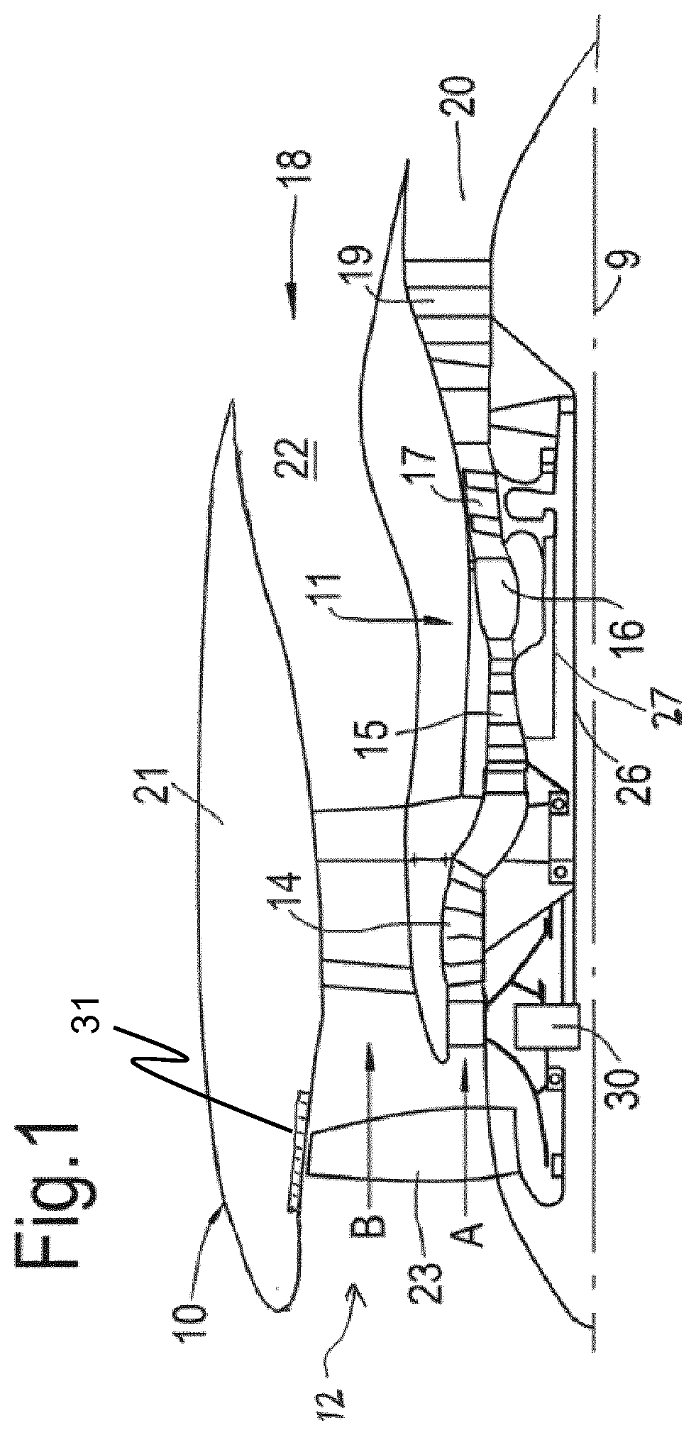
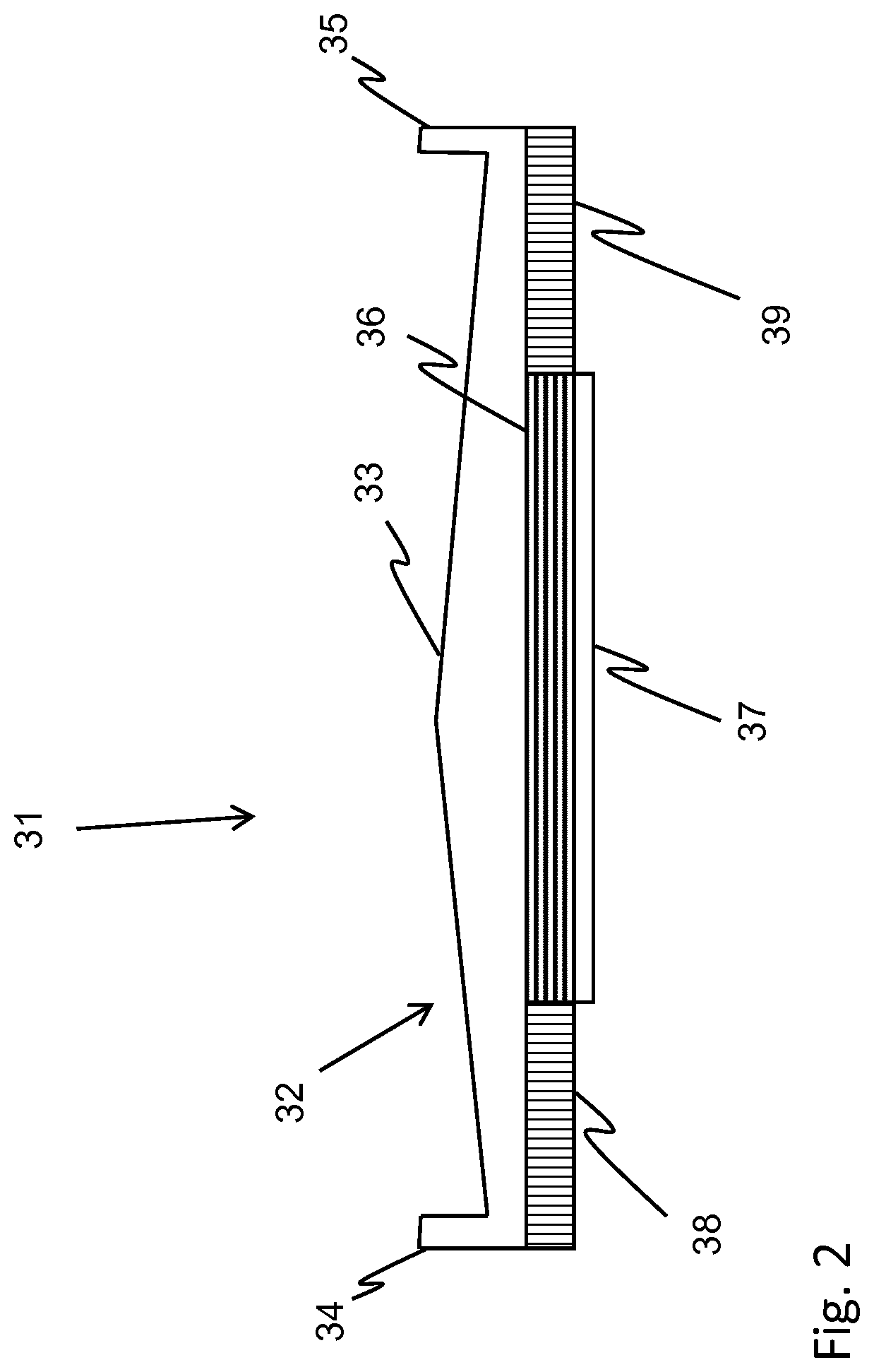
[0153]FIG. 1 illustrates a gas turbine engine 10 having a principal rotational axis 9. The engine 10 comprises an air intake 12 and a propulsive fan 23 that generates two airflows: a core airflow A and a bypass airflow B. The gas turbine engine 10 comprises a core 11 that receives the core airflow A. The engine core 11 comprises, in axial flow series, a low pressure compressor 14, a high-pressure compressor 15, combustion equipment 16, a high-pressure turbine 17, a low pressure turbine 19 and a core exhaust nozzle 20. A nacelle 21 surrounds the gas turbine engine 10 and defines a bypass duct 22 and a bypass exhaust nozzle 18. The bypass airflow B flows through the bypass duct 22. The fan 23 is attached to and driven by the low pressure turbine 19 via a shaft 26 and an epicyclic gearbox 30. A fan containment arrangement 31 extends around the fan 23 inboard the nacelle 21.

[0154]In use, the core airflow A is accelerated and compressed by the low pressure compressor 14 and directed into...


PUM


Abstract

A fan track liner for a fan containment arrangement for a gas turbine engine comprises a cellular impact structure and a supporting sub-laminate integrally formed with each other from a fibre-reinforced polymer material.

Description

CROSS-REFERENCE TO RELATED APPLICATIONS[0001]This application is a U.S. National Stage Application under 35 U.S.C. § 371 of International Application No. PCT / EP2019 / 067853, filed Jul. 3, 2019, which claims the benefit of priority to United Kingdom Application No. GB 1811549.3, filed Jul. 13, 2018, and the present application claims the benefit of the filing date of both of these prior applications, which are incorporated by reference in their entireties.FIELD[0002]The present disclosure concerns fan track liners and methods of manufacturing fan track liners.BACKGROUND[0003]Gas turbine engines include a fan having fan blades in front of the engine. The fan may be contained in a fan containment casing. In a failure event during operation, one of the fan blades may break off from the fan and impact the fan containment casing. This is generally referred to as a fan blade-off (FBO) event. After a turbine engine fan loses a blade, the loads on the fan containment casing rise well above th...

Claims


Application Information

Patent Timeline
IPC IPC(8): F01D21/04B29C63/34B29C64/118B29C70/32B29D24/00B29D99/00B33Y10/00B33Y30/00B33Y80/00F01D25/24
CPCF01D21/045B29C63/34B29C64/118B29C70/323B29D24/005B29L2031/7504B33Y10/00B33Y30/00B33Y80/00F01D25/24B29D99/006F05D2240/14F05D2250/283F05D2300/603F05D2300/612F05D2230/31F05D2300/6034F04D29/023B29C70/32B29D99/001Y02T50/60F04D29/526F05D2220/36F01D25/005
Inventor PELIN, RICARDO
Owner ROLLS ROYCE PLC
Learn More