
Keyboard structure

Inactive Publication Date: 2021-10-21
SILITEK ELECTRONICS DONGGUAN CO LTD
View PDF0 Cites 0 Cited by
  • Summary
  • Abstract
  • Description
  • Claims
  • Application Information

AI Technical Summary

Benefits of technology

The invention is a keyboard that improves its ability to resist water and dust. It does this by using a special design with a base, frame, and keys. Each key has a cap, a limiting structure, an elastic member, and a diaphragm switch element. This design prevents dust and moisture from getting inside the keyboard, making it more resistant to water and dust.

Problems solved by technology

However, dusts may easily enter the keyboard via the gap between two adjacent caps.
Meanwhile, if the keyboard is not covered with a waterproof cover, moisture also may easily enter the keyboard via the gap between two adjacent caps.

Method used


Image

  • Keyboard structure
  • Keyboard structure
  • Keyboard structure

Examples


first embodiment

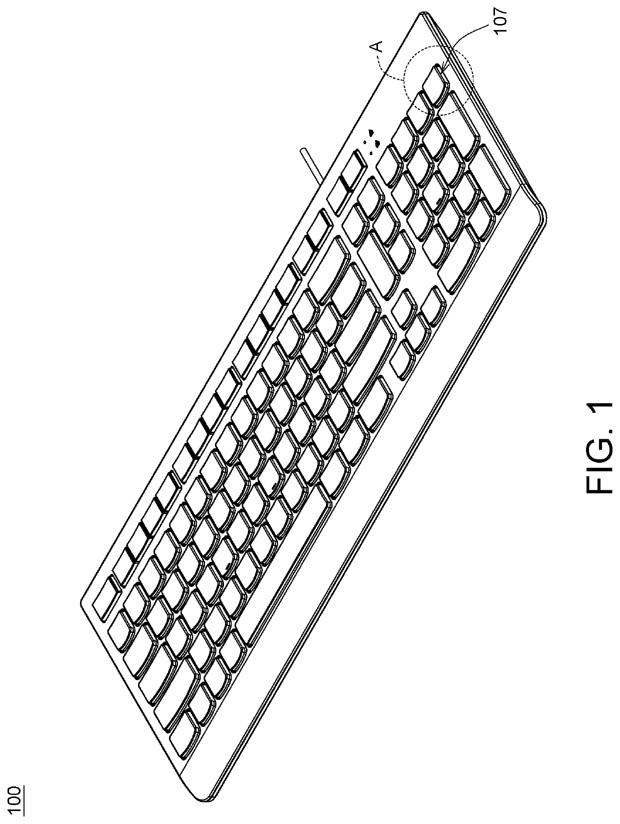
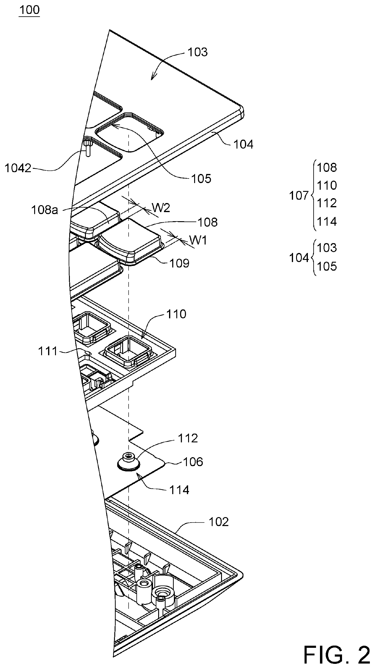
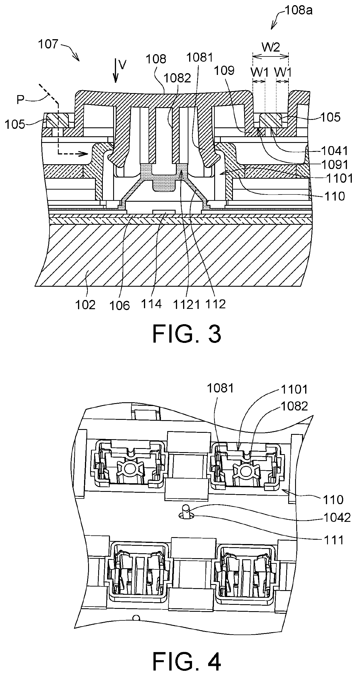
[0016]FIG. 1 is a schematic diagram of a keyboard structure 100 according to an embodiment of the present invention. FIG. 2 is an explosion diagram of a local area A of a keyboard structure 100 according to an embodiment of the present invention. FIG. 3 is a cross-sectional view of a key 107 of a keyboard structure 100 according to an embodiment of the present invention. Refer to FIG. 1, FIG. 2 and FIG. 3. In an embodiment, the keyboard structure 100 includes a base 102, a frame 104, a thin-film circuit board 106 and keys 107. The base 102 is located at the bottom of the keyboard structure 100 to support the thin-film circuit board 106 and the keys 107. The frame 104 is disposed on the base 102. Specifically, the frame 104 is fixed on the base 102 using a screw or a fastener.

[0017]The keys 107 are disposed on the base 102, and each key 107 represents at least one character, function key or symbol. The keys 107 form a keyboard structure 100 with a QWERTY layout or other layout. The k...

second embodiment

[0027]FIG. 6 is an explosion diagram of a local area of a keyboard structure 100′ according to an embodiment of the present invention. FIG. 7 is a cross-sectional view of a key 107 of a keyboard structure 100′ according to an embodiment of the present invention. Refer to FIG. 6 and FIG. 7. In the present embodiment, the keyboard structure 100′ includes a base 102, an outer frame portion 103, a frame 104, a thin-film circuit board 106 and several keys 107. Detailed structure of the base 102, the frame 104, the thin-film circuit board 106 and key 107 are already disclosed in the above embodiment and are not repeated here.

[0028]The present embodiment is different the above embodiment in that: the frame 104 only includes the spacers 105, the outer frame portion 103 surrounds the periphery of each of the spacers 105, the outer frame portion 103 and the limiting structure 110 are integrally formed in one piece, and the caps 108 of the keys 107 are separated by the spacers 105. That is, th...


PUM


Abstract

A keyboard structure including a base, a frame and several keys is provided. The frame is disposed on the base. The keys are disposed on the base and are separated from each other by the frame. From top to bottom, each key sequentially includes a cap, a limiting structure, an elastic member and a diaphragm switch element. The elastic member is disposed on the diaphragm switch element, the cap is disposed on the elastic member, and the limiting structure is engaged with the cap, such that the cap can move relative to the diaphragm switch element in a vertical direction. The surrounding surface of the cap has a flange, which contacts the bottom of the frame in the vertical direction. Thus, dusts or moisture can hardly infiltrate the keyboard structure and the waterproof and dustproof functions of the keyboard structure can be improved.

Description

[0001]This application claims the benefit of People's Republic of China application Serial No. 202010300017.4, filed Apr. 16, 2020, the subject matter of which is incorporated herein by reference.BACKGROUND OF THE INVENTIONField of the Invention[0002]The invention relates in general to a keyboard structure, and more particularly to a waterproof and dustproof keyboard structure.Description of the Related Art[0003]Conventional keyboard includes a cap, a scissor lift structure, an elastic member and a thin-film circuit board. The elastic member, disposed under the cap, provides an elastic restoring force to the cap. The scissor lift structure is configured to support the cap, such that when the cap is pressed, the cap can press the elastic member and transfer a downforce to trigger the switch element disposed on the thin-film circuit board.[0004]However, dusts may easily enter the keyboard via the gap between two adjacent caps. Meanwhile, if the keyboard is not covered with a waterproo...

Claims


Application Information

Patent Timeline
IPC IPC(8): H01H13/70H01H13/14H01H13/20
CPCH01H13/70H01H2233/07H01H13/20H01H13/14H01H13/705H01H13/7065H01H13/86H01H2211/006H01H2207/008H01H2223/002H01H2215/006H01H2235/016
Inventor WANG, KE-CHENG
Owner SILITEK ELECTRONICS DONGGUAN CO LTD
Learn More