
End effector positioning mechanism

a positioning mechanism and end effect technology, applied in the field of surgical instruments and devices, can solve the problems of increasing the risk of stroke and entering the blood circulation

Pending Publication Date: 2021-11-11
ATRICURE
View PDF3 Cites 0 Cited by
  • Summary
  • Abstract
  • Description
  • Claims
  • Application Information

AI Technical Summary

Benefits of technology

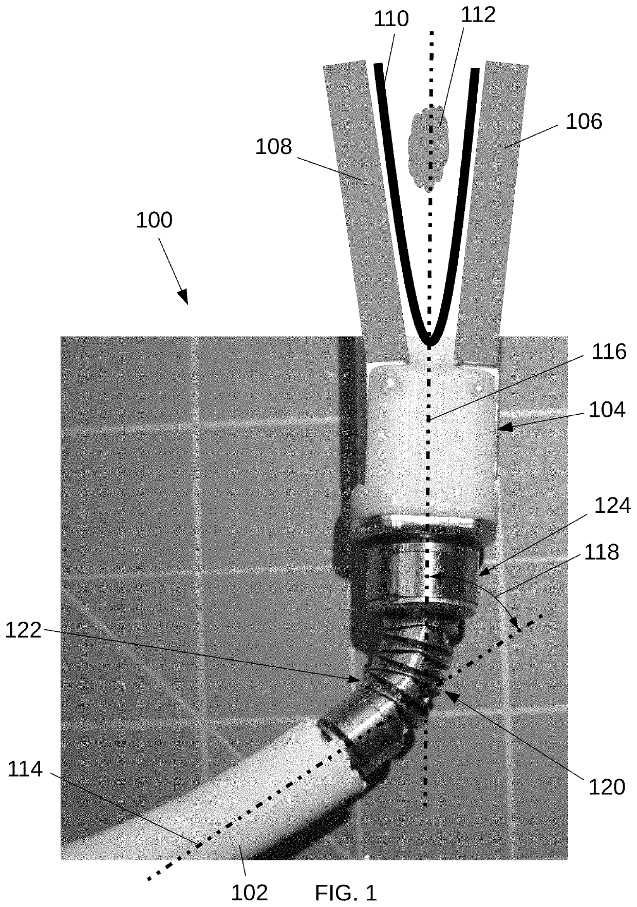
The present disclosure describes an improvement in the construction and operation of clip appliers and other surgical devices that may include rotatable and / or articulatable end effectors. These improvements may enhance the construction, operation, and methods of use of these surgical devices. Specifically, the patent discusses a method for excluding the left atrial appendage (a common heart arrhythmia that may increase the risk of stroke) in patients by using an occlusion clip. The difficulty of positioning the clip on the left atrial appendage may be reduced by utilizing a clip applier with an end effector that is repositionable, such as rotatable and / or articulatable. Additionally, the patent also discusses the use of tensioning the tension line to reduce gaps between adjacent segments of the clip and improve its performance.

Problems solved by technology

In some patients with atrial fibrillation, stagnant blood in the heart's left atrial appendage (“LAA”) may be a source of blood clots, which may enter the blood circulation and increase the risk of stroke.
The present disclosure contemplates that difficulties encountered in left atrial appendage exclusion procedures may include challenges in precisely positioning the occlusion clip at the desired location on the left atrial appendage using the clip applier.
This difficulty may be particularly relevant when the heart is accessed in a minimally invasive manner, such as via a small sub-xiphoid or sub-costal incision.

Method used


Image

  • End effector positioning mechanism
  • End effector positioning mechanism
  • End effector positioning mechanism

Examples


Embodiment Construction

[0026]Example embodiments according to the present disclosure are described and illustrated below to encompass devices, methods, and techniques relating to medical procedures. Of course, it will be apparent to those of ordinary skill in the art that the embodiments discussed below are examples and may be reconfigured without departing from the scope and spirit of the present disclosure. It is also to be understood that variations of the example embodiments contemplated by one of ordinary skill in the art shall concurrently comprise part of the instant disclosure. However, for clarity and precision, the example embodiments as discussed below may include optional steps, methods, and features that one of ordinary skill should recognize as not being a requisite to fall within the scope of the present disclosure.

[0027]The present disclosure includes, inter alia, surgical instruments and devices and related methods, and, more specifically, mechanisms for rotating and / or articulating end e...


PUM


Abstract

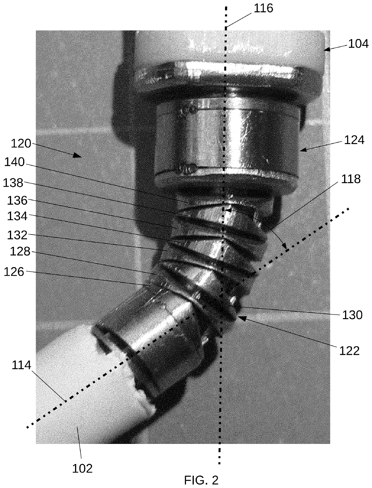
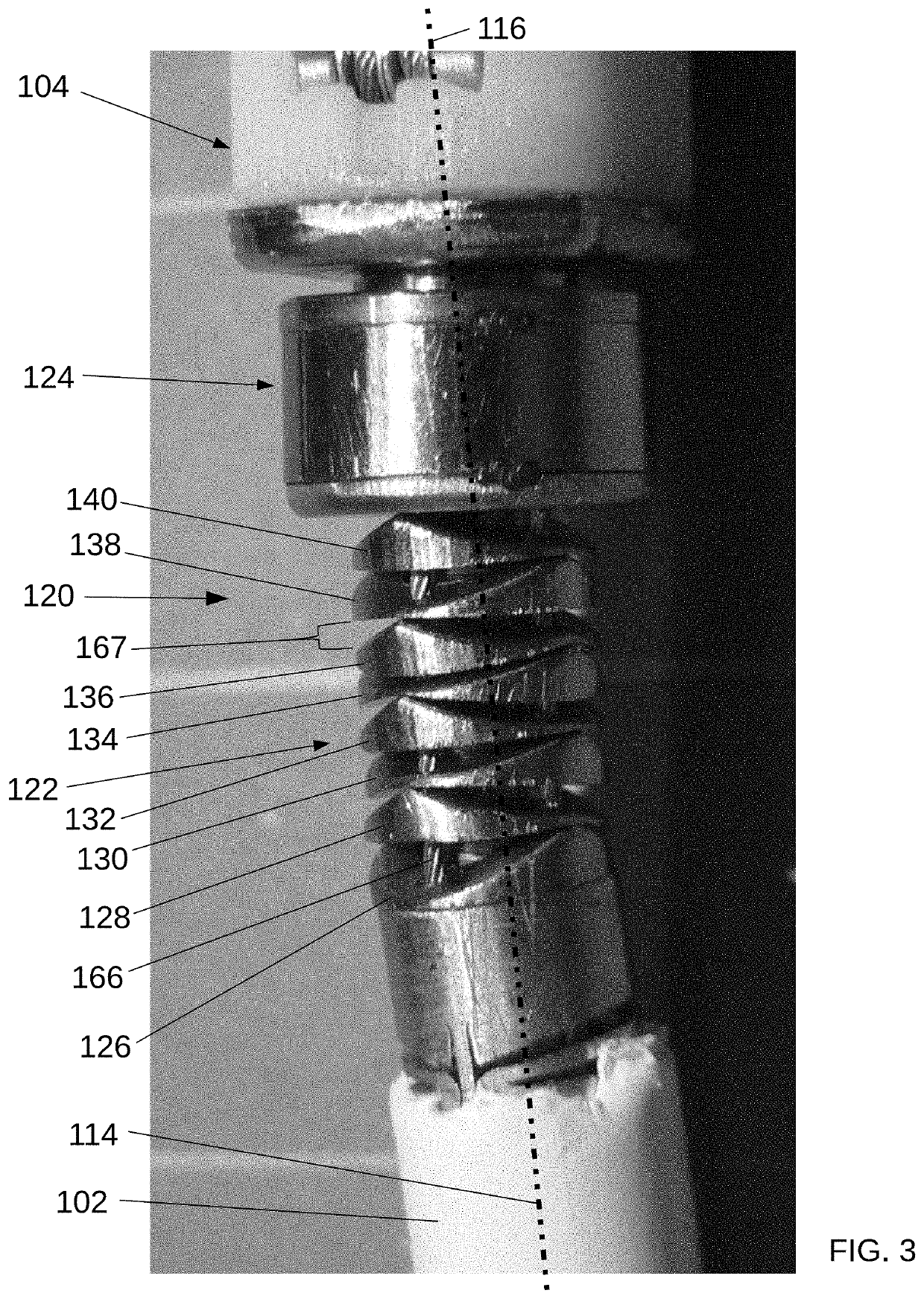
An end effector positioning mechanism for a surgical device may include an articulation mechanism including a plurality of tiltable segments disposed generally in a longitudinal row between an elongated shaft of a surgical device and an end effector of the surgical device. Each of the plurality of segments may be generally in the form of a flattened disk. At least one of the segments may include a proximal surface and / or a distal surface that is substantially planar and is oriented substantially orthogonally with respect to a central axis of the articulation mechanism. At least one of the segments may include a proximal surface and / or a distal surface including two transversely oriented, generally planar surfaces that meet along a substantially diametric peak.

Description

CROSS REFERENCE TO RELATED APPLICATION[0001]This application claims the benefit of U.S. Provisional Application No. 63 / 020,612, filed May 6, 2020, which is incorporated by reference.INTRODUCTION TO THE INVENTION[0002]The present disclosure is directed to surgical instruments and devices and related methods, and, more specifically, to mechanisms for rotating and / or articulating end effectors of surgical devices, and related methods.[0003]The present disclosure contemplates that atrial fibrillation is a common heart arrhythmia, affecting millions of people in the United States. In some patients with atrial fibrillation, stagnant blood in the heart's left atrial appendage (“LAA”) may be a source of blood clots, which may enter the blood circulation and increase the risk of stroke. Excluding the LAA, which may create electrical and / or fluidic isolation of the LAA, may be beneficial in terms of reducing the atrial fibrillation burden and / or reducing the risk of stroke for some patients. ...

Claims


Application Information

Patent Timeline
Patent Type & Authority Applications(United States)
IPC IPC(8): A61B17/128
CPCA61B17/1285A61B2017/00314A61B2017/00327A61B2017/00243
Inventor BANCHIERI, MICHAEL J.MONTI, MATTHEWIBRAHIM, TAMERMILLER, KENNETH L.STEPHANIAN, ARA M.MOREJOHN, DWIGHT P.
Owner ATRICURE
Learn More