Supercharge Your Innovation With Domain-Expert AI Agents!

Orthopedic broach

a technology of orthopedic broaches and latches, applied in the field of orthopedic broaches, can solve the problems of reducing the resistance provided to the bucking head or latch, preventing causing the broach to release, so as to prevent the latch from releasing the cutting tip, increase the force, and prevent the effect of further bending

Pending Publication Date: 2021-11-25
SMITH & NEPHEW INC +2
View PDF0 Cites 5 Cited by
  • Summary
  • Abstract
  • Description
  • Claims
  • Application Information

AI Technical Summary

Benefits of technology

[0032]In one embodiment, the linkage is a leaf spring, and, with the lever in the first position, the spring is in an unflexed position extending between the lever and the latch, and, with the lever in the second position, the spring transitions to a flexed position to exert an increased force onto the latch, the means for preventing the linkage from moving being arranged and configured to prevent the spring from unflexing in the second position and thus preventing the latch from releasing the cutting tip.
[0033]Embodiments of the present disclosure provide numerous advantages. For example, by incorporating one or more features of the present disclosure, in use, the spring coupling the lever to the latch, and hence the broach to the handle, is prevented from further bending, bowing, deflecting, moving, etc. prior to the point where the latch releases the broach. Thus arranged, the spring prevents the latch from moving to the second or released position, and thus prevents the broach from decoupling from the handle when subjected to excessive removal forces. In use, the spring provides increased resistance to decoupling of the broach from the handle.

Problems solved by technology

A disadvantage with the current design is that over time, the suspension bar or spring may become worn thus decreasing the amount of resistance provided to the bucking head or latch (e.g., thereby making it more likely that the rasp can be decoupled from the frame or handle).
However, if the force applied to the broach handle is too great, the broach handle can disconnect from the broach leaving the broach in the patient's intramedullary canal (e.g., application of a large extraction force can cause the broach to release from the bucking head or latch).

Method used


Image

  • Orthopedic broach
  • Orthopedic broach
  • Orthopedic broach

Examples


Embodiment Construction

[0044]Various features or the like of orthopedic broaches will now be described more fully hereinafter with reference to the accompanying drawings, in which one or more features of the orthopedic broaches will be shown and described. It should be appreciated that the various features or the like may be used independently of, or in combination, with each other. It will be appreciated that an orthopedic broach as disclosed herein may be embodied in many different forms and should not be construed as being limited to the embodiments set forth herein. Rather, these embodiments are provided so that this disclosure will convey certain features of the orthopedic broach to those skilled in the art.

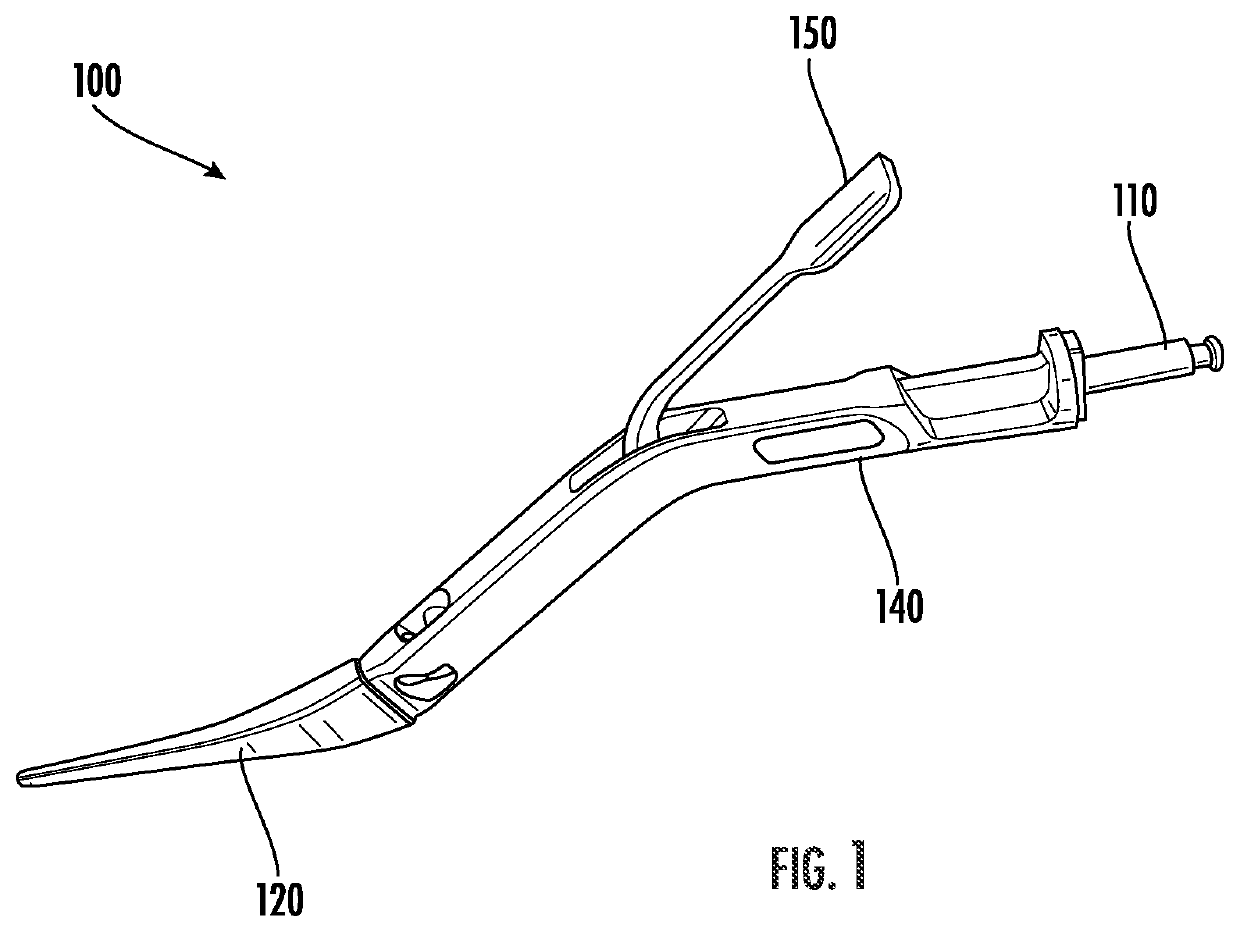
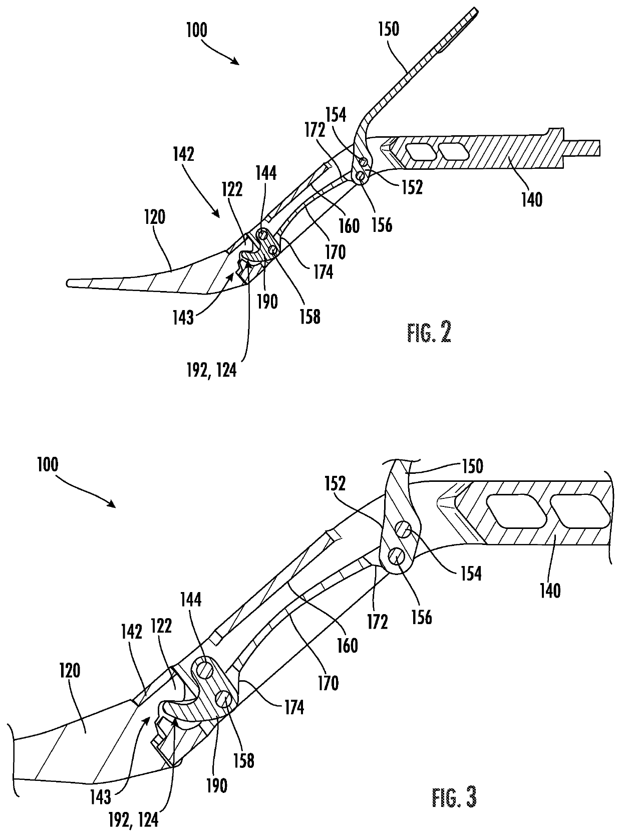
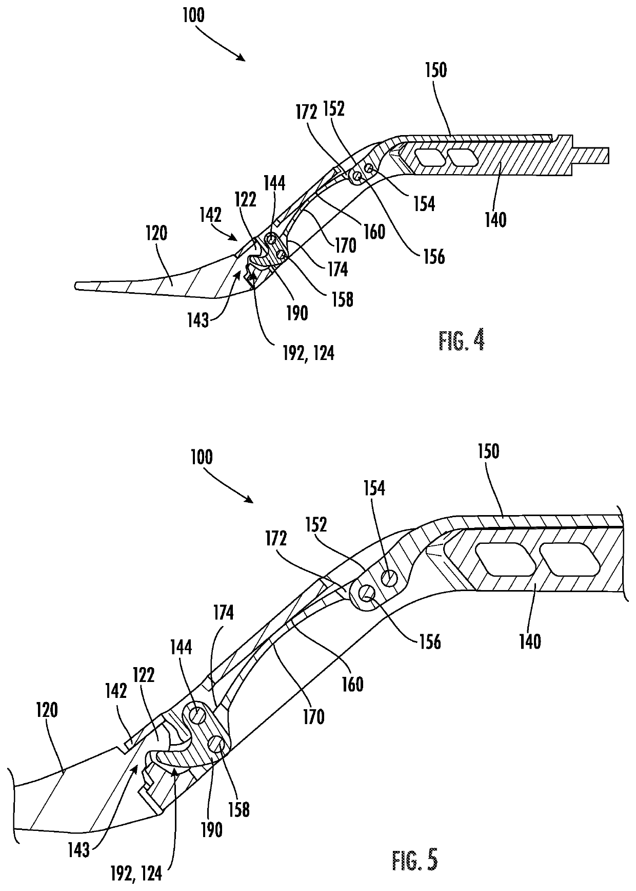
[0045]Disclosed herein is an orthopedic instrument such as, for example, an orthopedic broach including one or more features arranged and configured to provide an improved linkage or coupling mechanism for coupling a broach or cutting tip to a handle. More specifically, in accordance with one or m...


PUM


Abstract

An orthopedic broach is disclosed. The orthopedic broach includes a cutting tip and a broach handle. The broach handle includes a lever, a spring, and a latch. The lever is movably coupled to the handle and to an end of the spring. The latch is movably coupled to the handle and the opposite end of the spring. In use, the lever is movable from an opened position, where the latch is positioned in a released position, so that the cutting tip can be inserted into the handle, to a closed position where the latch is moved to an engaged position wherein the cutting tip is securely coupled to the latch, and thus the handle. The handle includes a spring stop to prevent the spring from further deflection to prevent the latch from moving to the released position and thus prevent decoupling of the cutting tip when excessive forces are applied.

Description

CROSS-REFERENCE TO RELATED APPLICATIONS[0001]This is a non-provisional of, and claims the benefit of the filing date of, pending U.S. provisional patent application No. 63 / 028,168, filed May 21, 2020, entitled “Orthopedic Broach,” the entirety of which application is incorporated by reference herein.FIELD OF THE INVENTION[0002]The present disclosure is directed to orthopedic instruments such as, an orthopedic broach, and more particularly, to an improved linkage or coupling mechanism for coupling a broach or cutting tip to a handle to prevent the broach or cutting tip from loosening or breaking away from the handle.BACKGROUND[0003]Orthopedic instruments such as, for example, an orthopedic broach, rasp, cutting instrument, etc. (terms used interchangeably herein without the intent to limit) are well known. In use, a broach is used during, for example, hip arthroplasty surgeries. In use, the surgeon uses the broach to prepare an inner surface of a patient's intramedullary canal to rec...

Claims


Application Information

Patent Timeline
Patent Type & Authority Applications(United States)
IPC IPC(8): A61B17/16A61B90/00
CPCA61B17/1659A61B2017/00477A61B90/03A61B17/1613A61B2090/034A61B17/1668A61B17/92A61B2017/00473A61B2017/00464
Inventor ZIMMERMAN, JACOB
Owner SMITH & NEPHEW INC
Features
  • R&D
  • Intellectual Property
  • Life Sciences
  • Materials
  • Tech Scout
  • Unparalleled Data Quality
  • Higher Quality Content
  • 60% Fewer Hallucinations
Learn More