
Gyroscope with mass pairs

Pending Publication Date: 2021-12-02
MURATA MFG CO LTD
View PDF0 Cites 3 Cited by
  • Summary
  • Abstract
  • Description
  • Claims
  • Application Information

AI Technical Summary

Benefits of technology

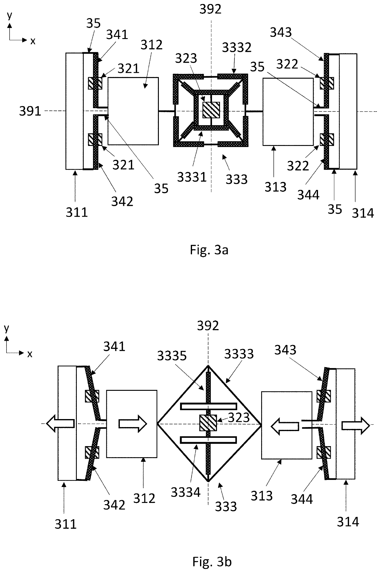
The present patent is about a simple and strong gyroscope structure that uses four Coriolis masses to measure angular rotation. By aligning these masses on the same axis and connecting them with coupling and suspension structures, the orientation of the measurement can be accurately measured without taking up too much space in a different direction. This arrangement can be used to create a compact and strong xy gyroscope, or even more robust versions with two such systems placed side by side. Overall, this patent provides a way to create a reliable and durable gyroscope that can measure rotation with high accuracy.

Problems solved by technology

A general problem in gyroscope is that the oscillation of the proof masses in these two modes should preferably not be perturbed by external disturbances, for example vibrations in surrounding elements.
A simple MEMS gyroscope may be constructed utilizing only one oscillating proof mass, but the output signal of such a gyroscope will typically be very noisy when external vibrations are present at frequencies close to the operating frequency.
One-mass gyroscopes would be practical only at operating frequencies above 50 kHz, but in these frequencies the sensitivity of the gyroscope may be very low and other disturbing effects, such as quadrature signals arising from manufacturing imperfections, often become very prominent.
Also, the unbalanced drive mode of the single mass drive causes energy leakage from the drive mode due to the reaction forces of the drive oscillation.
This will induce all kinds of issues; increase the drive force needed for operation, stability issues, requirements for hard die attachment. etc.

Method used


Image

  • Gyroscope with mass pairs
  • Gyroscope with mass pairs
  • Gyroscope with mass pairs

Examples


embodiment

Y-Axis Embodiment

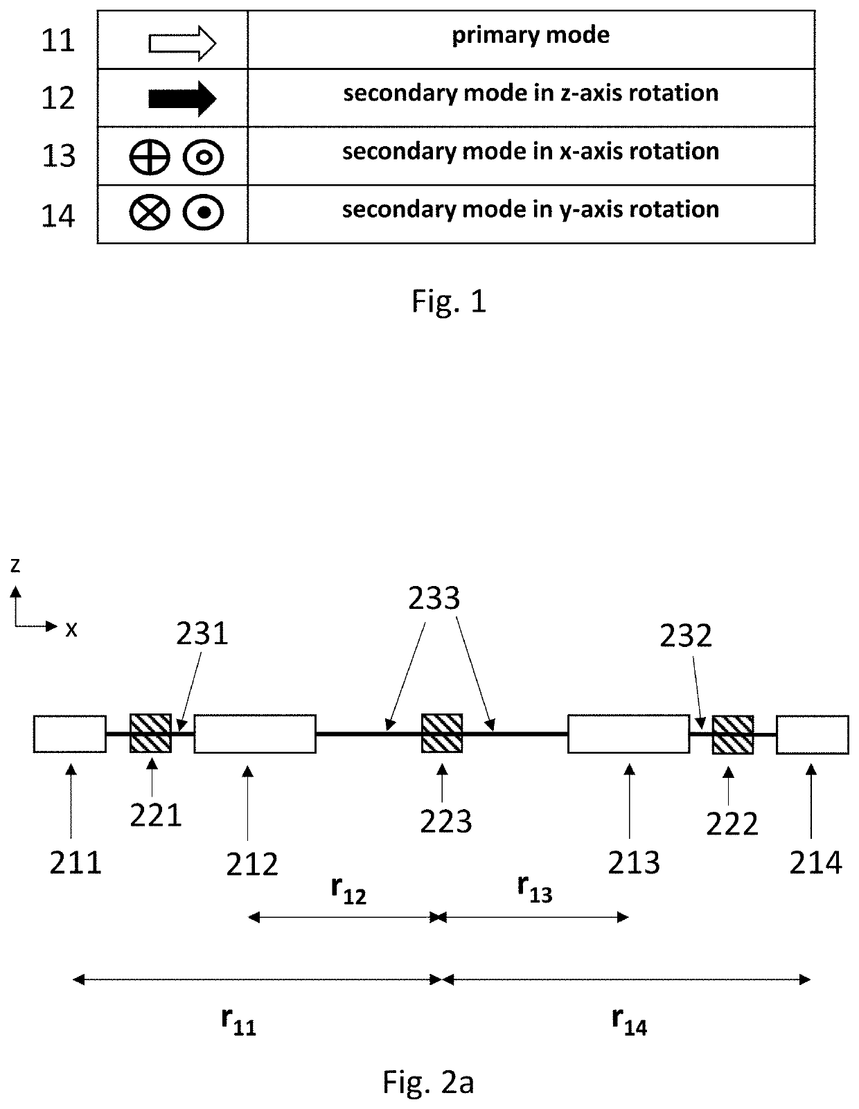
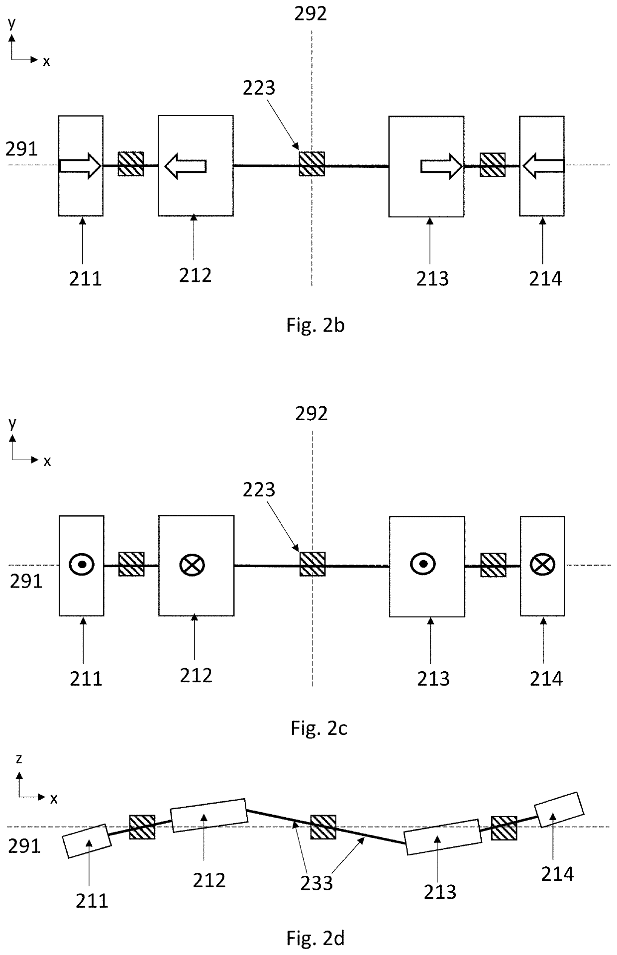
[0041]FIG. 2a illustrates schematically a gyroscope in the xz-plane. The gyroscope comprises a first set of Coriolis masses which includes first and second Coriolis masses 211 and 212, and third and fourth Coriolis masses 213 and 214. The first center point is located at the first central anchor point 223. The first side of the y1-axis is thereby shown on the left side of the first central anchor point 223, and the second side of the y1-axis is shown on the right side of the first central anchor point 223 in FIG. 2. The gyroscope is configured to measure angular rotation about the y-axis. In other words, the y-axis may in this case be called the input axis or measurement axis of the gyroscope.

[0042]The set of first peripheral anchor points is here illustrated simply as one anchor point 221, but it may in practice include several anchor points. The first peripheral suspension arrangement 231 is here illustrated merely as a connecting bar between the first and second ...


PUM


Abstract

A microelectromechanical gyroscope comprising first, second, third and fourth Coriolis masses, arranged in that order on an x-axis. In the primary oscillation mode, the Coriolis masses are configured to oscillate so that the second and third Coriolis masses move in linear translation along the x-axis away from a center point when the first and fourth Coriolis masses move in linear translation along the x-axis towards the first center point, and vice versa. When the gyroscope undergoes rotation about a y-axis which is perpendicular to the x-axis, the Coriolis masses are configured to oscillate so that the first, second, third and fourth Coriolis masses undergo vertical motion in a z-direction, wherein the first and third Coriolis masses move up when the second and fourth Coriolis masses move down, and vice versa.

Description

FIELD OF THE DISCLOSURE[0001]This disclosure relates to microelectromechanical gyroscopes, and more particularly to gyroscopes where an oscillating proof mass system is used to measure angular rotation at least about one rotation axis which lies in the device plane.BACKGROUND OF THE DISCLOSURE[0002]In microelectromechanical (MEMS) gyroscopes proof masses should preferably be easily set to oscillate in a primary oscillation mode (which may also be called the drive oscillation mode) and also easily undergo oscillation in a secondary oscillation mode (which may also be called the sense oscillation mode) induced by the Coriolis force. A general problem in gyroscope is that the oscillation of the proof masses in these two modes should preferably not be perturbed by external disturbances, for example vibrations in surrounding elements. A gyroscope should preferably be unperturbed by both linear and rotational vibrations so that its output signal is determined only by the angular rotation ...

Claims


Application Information

Patent Timeline
IPC IPC(8): G01C19/5712
CPCG01C19/5712G01C19/574G01C19/5747
Inventor BLOMQVIST, ANSSIRYTKÖNEN, VILLE-PEKKA
Owner MURATA MFG CO LTD
Learn More