Centrifugal fan

Pending Publication Date: 2021-12-09
ASUSTEK COMPUTER INC
View PDF0 Cites 0 Cited by
  • Summary
  • Abstract
  • Description
  • Claims
  • Application Information

AI Technical Summary

Benefits of technology

The patent improves the heat dissipation efficiency of a centrifugal fan by expanding the air channel in a way that enhances the fan's performance and reduces noise. This is achieved by using a centrifugal fan with a gradual expansion of the air channel, which allows for better airflow and improved heat dissipation.

Problems solved by technology

However, in the conventional art, when the blade contour line of the fan is designed, an airflow occurred between the blades is not taken into consideration, and it is easy to generate eddy currents.
As a result, the performance of the fan is reduced, and a large amount of airflow noise are generated.

Method used


Image

  • Centrifugal fan
  • Centrifugal fan
  • Centrifugal fan

Examples


Embodiment Construction

[0012]More detailed descriptions of the specific embodiments of the disclosure are provided below with reference to the accompanying drawings. The features and advantages of the disclosure are described more clearly according to the following description and claims. It is to be noted that all of the drawings use very simplified forms and imprecise proportions, only being used for assisting in conveniently and clearly explaining the objective of the embodiments of the disclosure.

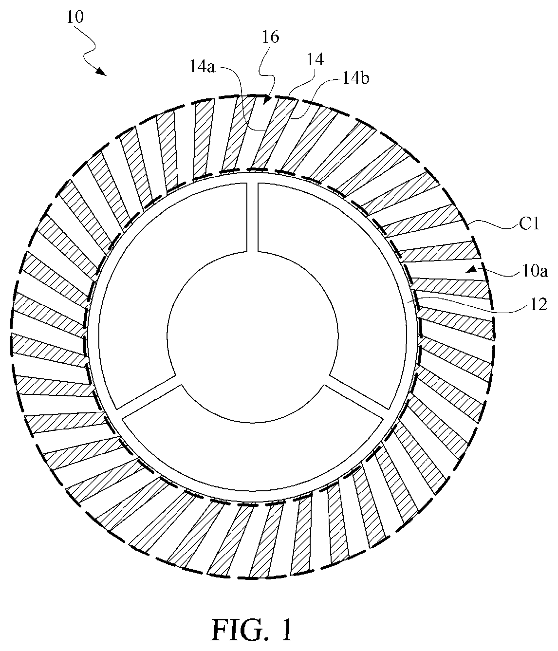
[0013]FIG. 1 is a schematic top view of an embodiment of a centrifugal fan according to the disclosure. The centrifugal fan 10 is applicable to an electronic device such as a notebook computer, a desktop computer, or a mainboard, to improve heat dissipation efficiency of the electronic device.

[0014]As shown in the figure, the centrifugal fan 10 includes a shaft 12 and a plurality of blades 14. The shaft 12 is connected to a driving motor. The blades 14 are disposed on the shaft 12 and surround the shaft 12, a...


PUM


Abstract

A centrifugal fan is provided. The centrifugal fan includes a shaft and a plurality of blades. The blades is disposed on the shaft and surround the shaft, and outer edges of the blades define a circle. The circle includes an outer region adjacent to a boundary of the circle, each of the blades includes a first contour line and a second contour line within the outer region, and the neighboring blades include an air channel therebetween, which expands toward the outer edges of the blades according to an interval expanding ratio.

Description

CROSS-REFERENCE TO RELATED APPLICATION[0001]This application claims the priority benefit of Taiwan application serial No. 109118897, filed on Jun. 5, 2020. The entirety of the above-mentioned patent application is hereby incorporated by reference herein and made a part of the specification.BACKGROUND OF THE INVENTIONField of the Invention[0002]The disclosure relates to a fan, and in particular, to a centrifugal fan for an electronic device.Description of the Related Art[0003]A centrifugal fan is formed by a plurality of blades arranged in a ring shape. When the fan runs, airflow flows in a centrifugal direction through channels between blades, and then flows into a fan frame channel of the fan.[0004]Generally, performance of the fan is adjusted by changing a design of a blade contour line and a quantity of blades. However, in the conventional art, when the blade contour line of the fan is designed, an airflow occurred between the blades is not taken into consideration, and it is eas...

Claims


Application Information

Patent Timeline
IPC IPC(8): F04D29/30F04D29/66F04D29/28F04D25/08
CPCF04D29/30F04D25/08F04D29/281F04D29/667F04D29/282
Inventor LIN, HSIN-CHENCHIOU, ING-JER
Owner ASUSTEK COMPUTER INC
Why Eureka
Try Eureka