
Heat sink

Inactive Publication Date: 2008-03-27
ASIA VITAL COMPONENTS SHENZHEN CO LTD
View PDF14 Cites 1 Cited by
  • Summary
  • Abstract
  • Description
  • Claims
  • Application Information

AI Technical Summary

Benefits of technology

[0006]Accordingly, the present invention is directed to a heat sink having an air inlet at the air inlet side such that an arched side of the air inlet is adopted to smoothly guide air through the air inlet side and thereby increase the efficiency of heat dissipation and as well as reduce the noise.
[0007]According to an aspect of the present invention, the air inlet side comprises a plurality of blades connected to a ring with a supporting chassis for increasing the volume and pressure of the airflow, and also avoids any objects from entering therein.
[0008]According to another aspect of the present invention, the air outlet side comprises no barricade to disturb or resist the airflow. Thus, the noise may be reduced and surface area of the heating element surface area coming in direct contact with air is substantially increased, and thus the heat dissipation effect may be effectively increased.
[0009]According to another aspect of the present invention, the air inlet protrudes out of the ring, wherein the protruding portion extends up to a vertical distance such that the dimension of the air inlet is larger than that of the air outlet side to increase the airflow area.
[0010]In accordance with the above purposes, the present invention provides a heat sink comprising a ring, an air inlet, a securing portion and a fan. The ring comprises an air inlet side and an air outlet side on the two sides thereof, respectively. The air inlet is positioned along the air inlet side of the ring. The air inlet comprises an arched side having at least one arch that extends outwardly along axial direction and the horizontal direction of the ring. The securing portion comprises a supporting chassis and a plurality of blades. The blades position the supporting chassis in the air tunnel of the ring close to the air inlet side. The fan may be positioned axially inverted on the supporting chassis of the securing portion. Thus, the side of the fan facing opposite to the securing portion corresponds to a heating element positioned at the air outlet side. The blades of the air inlet smoothly guide the air through the air inlet side. The blades are also adopted for increasing the volume and pressure of the airflow. Furthermore, there is no barricade blocking the air from flowing to the air outlet side. Thus, the heat dissipation can be promoted and the noise can be reduced.

Problems solved by technology

However, above conventional heat sink has the following defects.
Thus, this phenomenon increases the noise.

Method used


Image

  • Heat sink
  • Heat sink
  • Heat sink

Examples


Embodiment Construction

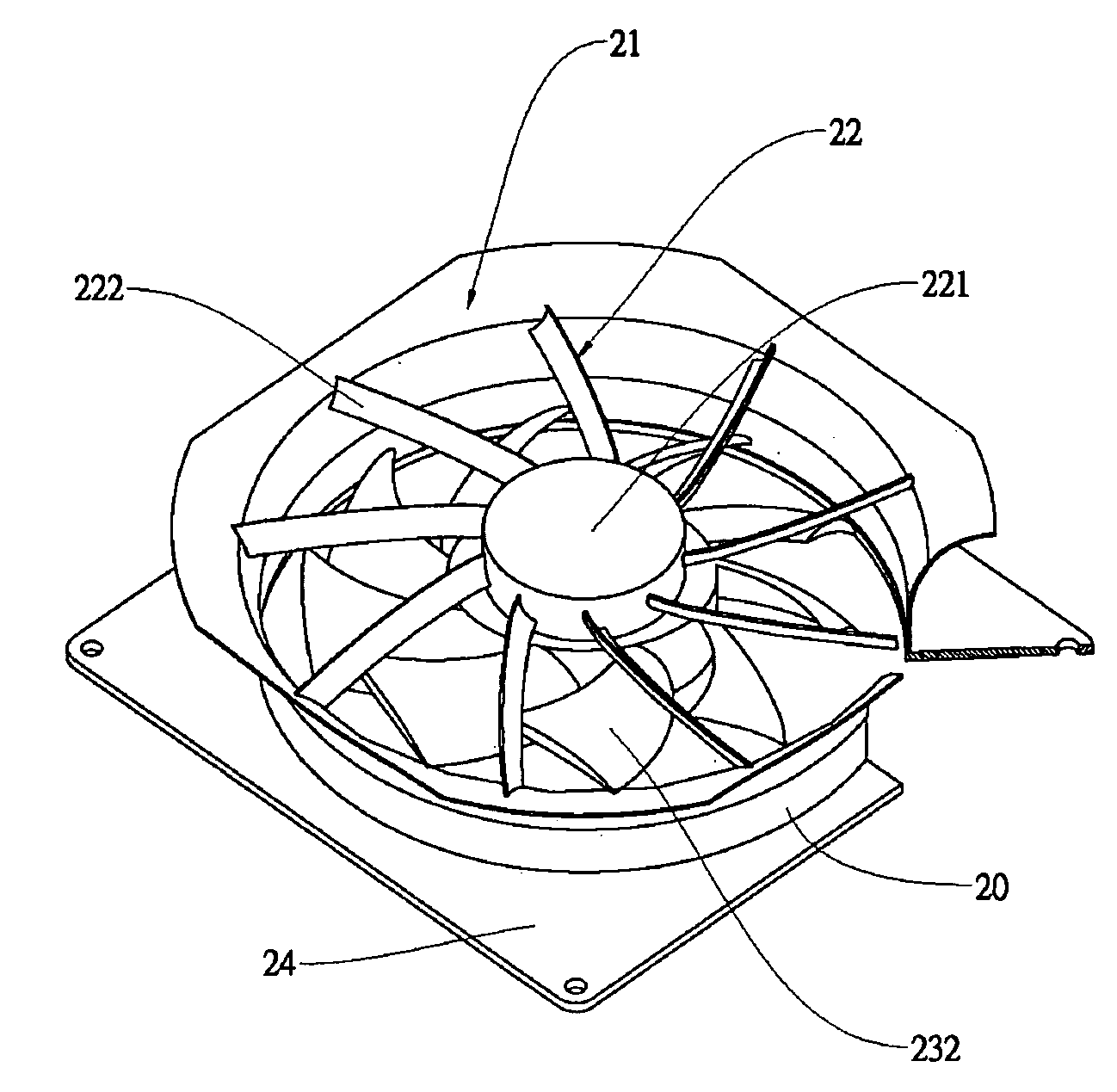
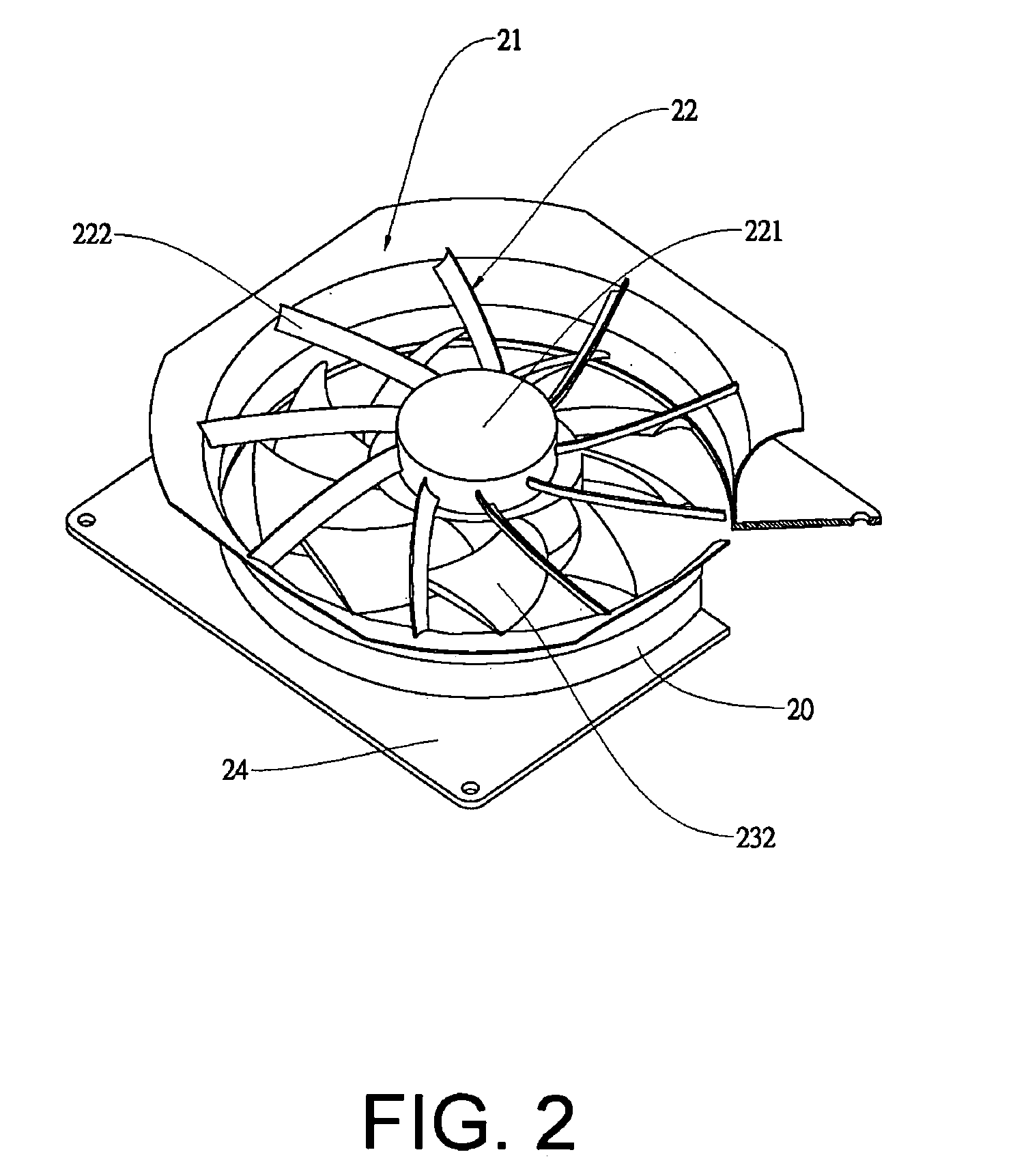
[0018]Referring to FIGS. 2 and 3, the structure of a heat sink according to an embodiment of the present invention comprises a ring 20, an air inlet 21, a securing portion 22 and a fan 23. The ring 20 is vertically positioned and comprises an air inlet side 201 and an air outlet side 202. The air inlet 21 vertically protrudes outwards along the ring 20 in a horizontal direction forming an arched side 211 with at least one arch structure. The arched side 211 may comprise a smooth shape, a trumpet shape or a stair-case shape. The ring 20 comprises a protruding portion 212 vertically protruding there-from. The dimension of the air inlet 21 is slightly larger than that of the air outlet side 202. Thus, the airflow area is significantly increased.

[0019]The securing portion 22 comprises a support chassis 221 and a plurality of blades 222. The support chassis 221 is positioned on the air inlet side 201 of the ring 20, and the blades 222 are radially positioned connecting the supporting cha...


PUM


Abstract

A heat sink is disclosed. The heat sink comprises a ring, an air inlet, a securing portion and a fan. The ring comprises an air inlet side and an air outlet side, wherein the air outlet side corresponds to at least one heating element. The air inlet vertically protrudes outwards along the ring in a horizontal direction forming an arched side having at least one arch structure, wherein the arched side protrudes out of the ring. The securing portion comprises a supporting chassis positioned on said air inlet side and a plurality of blades radially positioned connecting the supporting chassis and the ring. The fan comprises a hub and a plurality of blades positioned around the hub and is positioned inverted on said supporting chassis, wherein a side of the fan facing opposite to the securing portion correspond to the heating element.

Description

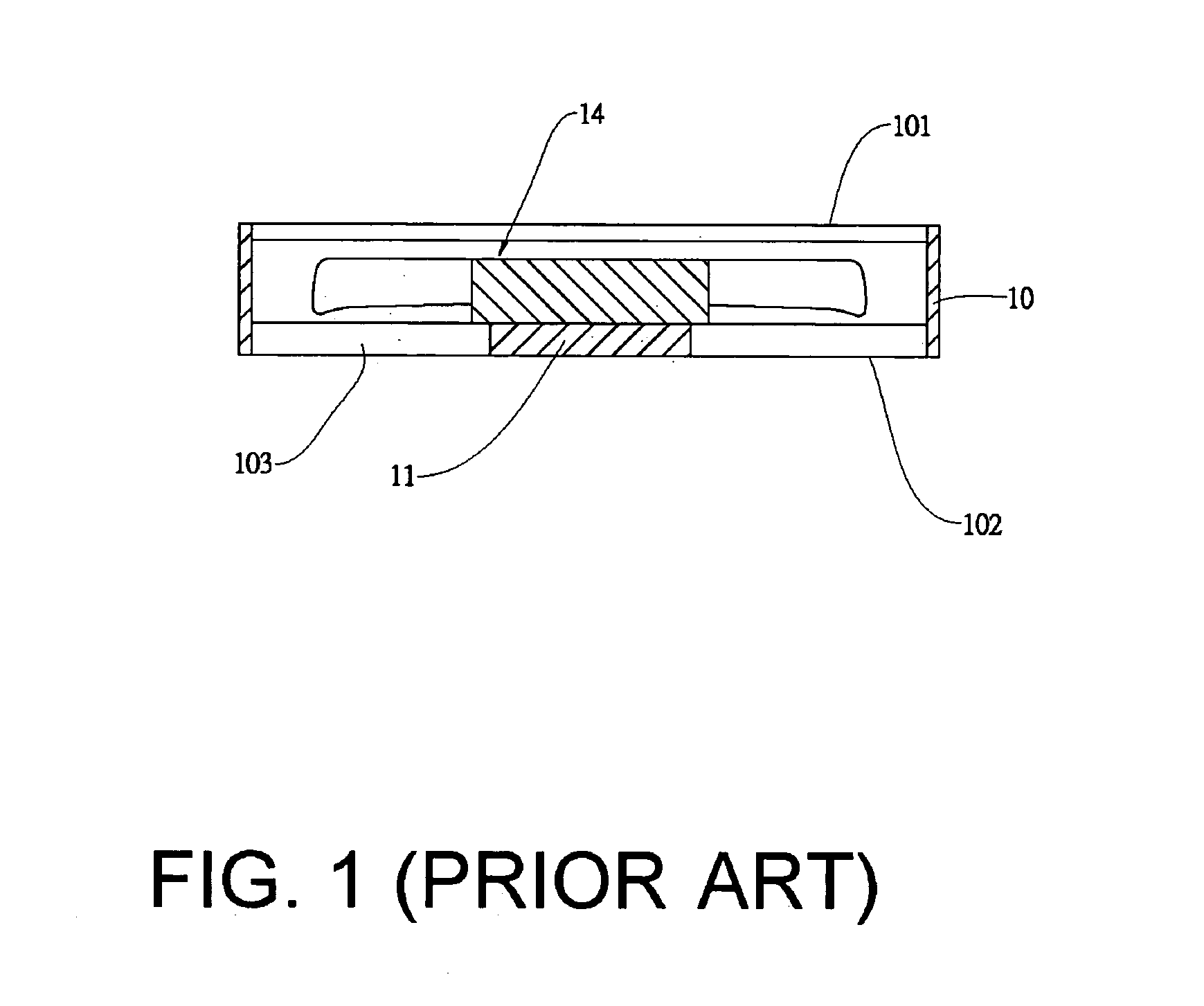
BACKGROUND OF THE INVENTION[0001]1. Field of the invention[0002]The present invention generally relates to a heat sink, and more particularly to a heat sink having fan positioned inverted on an air inlet.[0003]2. Description of the Related Art[0004]The conventional heat sink, as shown in FIG. 1, comprises a ring 10 having an air inlet side 101 and an air outlet side 102 respectively disposed on the two sides thereof. A supporting chassis 11 is positioned on the air outlet side 102 and a plurality of ribs 103 are disposed connecting the ring 10 and the supporting chassis 11 to secure the supporting chassis 11. A fan 14 is axially and rotatably positioned on the supporting chassis 11. Thus, a portion of the fan 14 not connected to the supporting chassis 11 is positioned facing the air inlet side 101. The ring 10 and the air inlet side 101 are vertically positioned. When the fan 14 rotates, the air flows through the air inlet side 101 and then the fan 14 blows the air out via the air o...

Claims


Application Information

Patent Timeline
IPC IPC(8): H05K7/20
CPCH01L23/467H01L2924/0002H01L2924/00
Inventor CHIA, TZU-CHOU
Owner ASIA VITAL COMPONENTS SHENZHEN CO LTD
Learn More