Heat dissipation module and heat dissipation method thereof

Active Publication Date: 2020-07-16
WISTRON CORP
View PDF0 Cites 0 Cited by
  • Summary
  • Abstract
  • Description
  • Claims
  • Application Information

AI Technical Summary

Benefits of technology

The invention provides a heat dissipation module and method that can effectively improve heat dissipation efficiency. The technology controls the voltage to adjust the temperature of the cooler, based on the sensor signal of the heat source. This enables the efficient dissipation of heat and prevents damage to the system or device.

Problems solved by technology

Once the rated compatible tolerance temperature of the chipset is exceeded, the system may experience abnormalities of uncertainty.
However, since the air cooling method uses air at a normal temperature (e.g., 25°) as the medium, its heat dissipation efficiency is limited.
At this time, if heat is dissipated only through air at the normal temperature, the dissipation effect of the high temperature instantaneously generated by the CPU is relatively limited.
Such a fan speed control method not only fails to respond in real time, but is also likely to have switching losses of the switch that cannot be precisely controlled.
In addition, the volume of the heat dissipation module currently available cannot be adjusted according to the user's requirement.
When there is requirement for a higher performance and a higher frequency, it is necessary to have a larger heat dissipation area on the heat dissipation module to increase the heat dissipation capability, which results in the need to redesign the heat dissipation module and further increases the design cost.

Method used


Image

  • Heat dissipation module and heat dissipation method thereof
  • Heat dissipation module and heat dissipation method thereof
  • Heat dissipation module and heat dissipation method thereof

Examples


Embodiment Construction

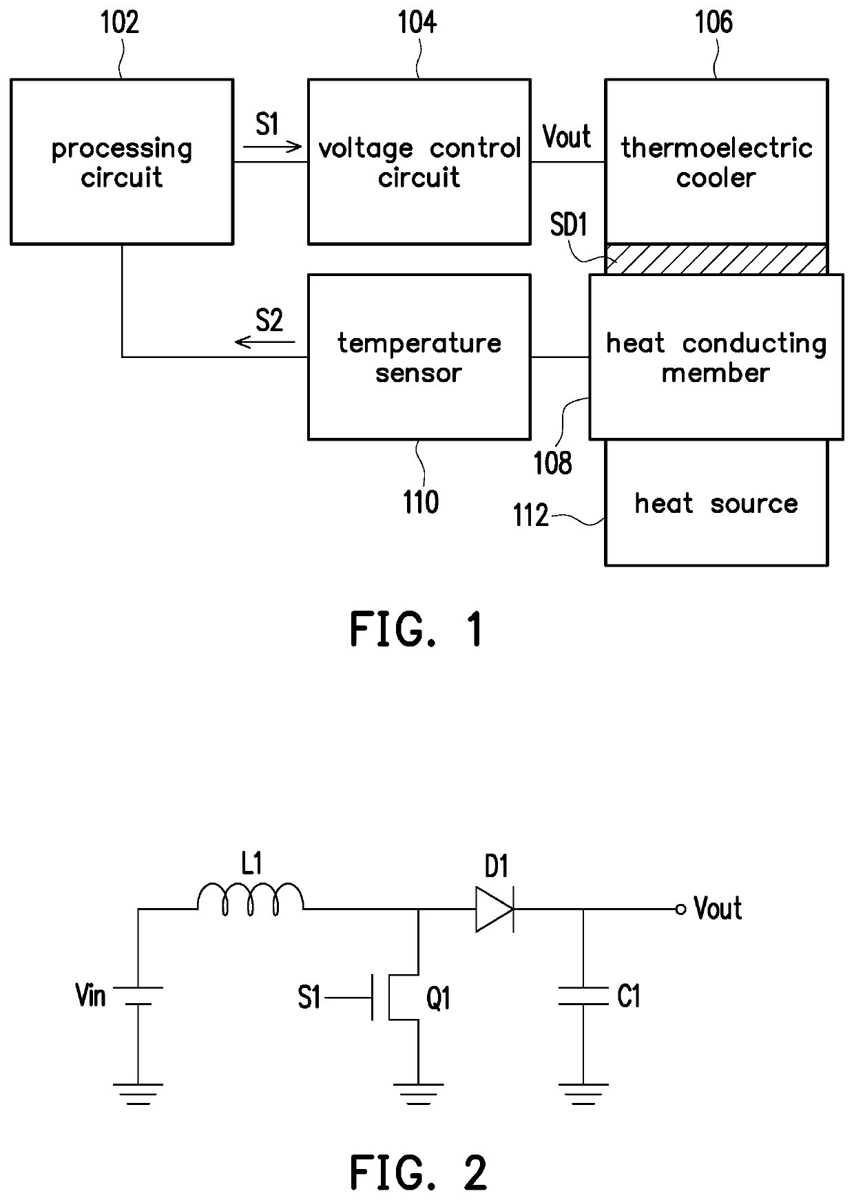
[0025]FIG. 1 is a schematic view of a heat dissipation module according to an embodiment of the invention. Referring to FIG. 1, the heat dissipation module may include a processing circuit 102, a voltage control circuit 104, a thermoelectric cooler 106, a heat conducting member 108, and a temperature sensor 110. The heat conducting member 108 is connected to a heat source 112, and the heat source 112 may be, for example, a device that generates thermal energy during operation such as a CPU or a display chip, but the invention is not limited thereto. The heat conducting member 108 may include, for example, a metal material having a high thermal conductivity such as an aluminum alloy, a silver alloy, or a copper alloy. The voltage control circuit 104 is coupled to the processing circuit 102 and the thermoelectric cooler 106. A cold side SD1 of the thermoelectric cooler 106 is disposed on the heat conducting member 108. Moreover, the processing circuit 102 is further coupled to the tem...


PUM


Abstract

A heat dissipation module and a heat dissipation method thereof are provided. A cold side of a thermoelectric cooler is disposed on a heat conducting member. A processing circuit controls a voltage control circuit to provide an output voltage to the thermoelectric cooler according to a temperature sensing signal generated by a temperature sensor sensing a temperature of the heat conducting member, so as to adjust a temperature of the cold side of the thermoelectric cooler to dissipate heat for a heat source.

Description

CROSS-REFERENCE TO RELATED APPLICATION[0001]This application claims the priority benefit of Taiwan application serial no. 108101555, filed on Jan. 15, 2019. The entirety of the above-mentioned patent application is hereby incorporated by reference herein and made a part of this specification.BACKGROUND OF THE INVENTIONField of the Invention[0002]The disclosure relates to a heat dissipation module and a heat dissipation method thereof, and more particularly, to a high-efficiency heat dissipation module and a heat dissipation method thereof.Description of Related Art[0003]With the advancement and demand of technology, a lot of simulation software, graphics software, and game software require high-performance computing capacity and a lot of central processing unit (CPU) resources, either in a desktop or a laptop. In order to improve the working efficiency of the CPU in response to highly complex computations and operations, operating and maintaining the CPU at a high clock rate will be...

Claims


Application Information

Patent Timeline
IPC IPC(8): F25B21/02
CPCF25B2321/0212F25B2321/025F25B21/02G06F1/20G05D23/20G06F2200/201
Inventor SHEN, CHIH-TENGWAN, LIANG-FANG
Owner WISTRON CORP
Why Eureka
Try Eureka