Thermal sensing bulb containing a ballast material for an expansion valve

Pending Publication Date: 2021-12-09
PARKER HANNIFIN CORP
View PDF0 Cites 0 Cited by
  • Summary
  • Abstract
  • Description
  • Claims
  • Application Information

AI Technical Summary

Benefits of technology

[0007]The present invention provides an improved thermal sensing bulb for an expansion valve that contains a ballast material including alumina. The alumina ballast material may be in the form of a plurality of discrete particles. The alumina ballast material ma

Problems solved by technology

A long-standing problem with thermostatic expansion valves (TEVs) in traditional refrigerant systems is a “hunting” phenomenon, which is the excessive cycling/oscillation of thermostatic control valves in response to transient changes in the

Method used


Image

  • Thermal sensing bulb containing a ballast material for an expansion valve
  • Thermal sensing bulb containing a ballast material for an expansion valve
  • Thermal sensing bulb containing a ballast material for an expansion valve

Examples


Embodiment Construction

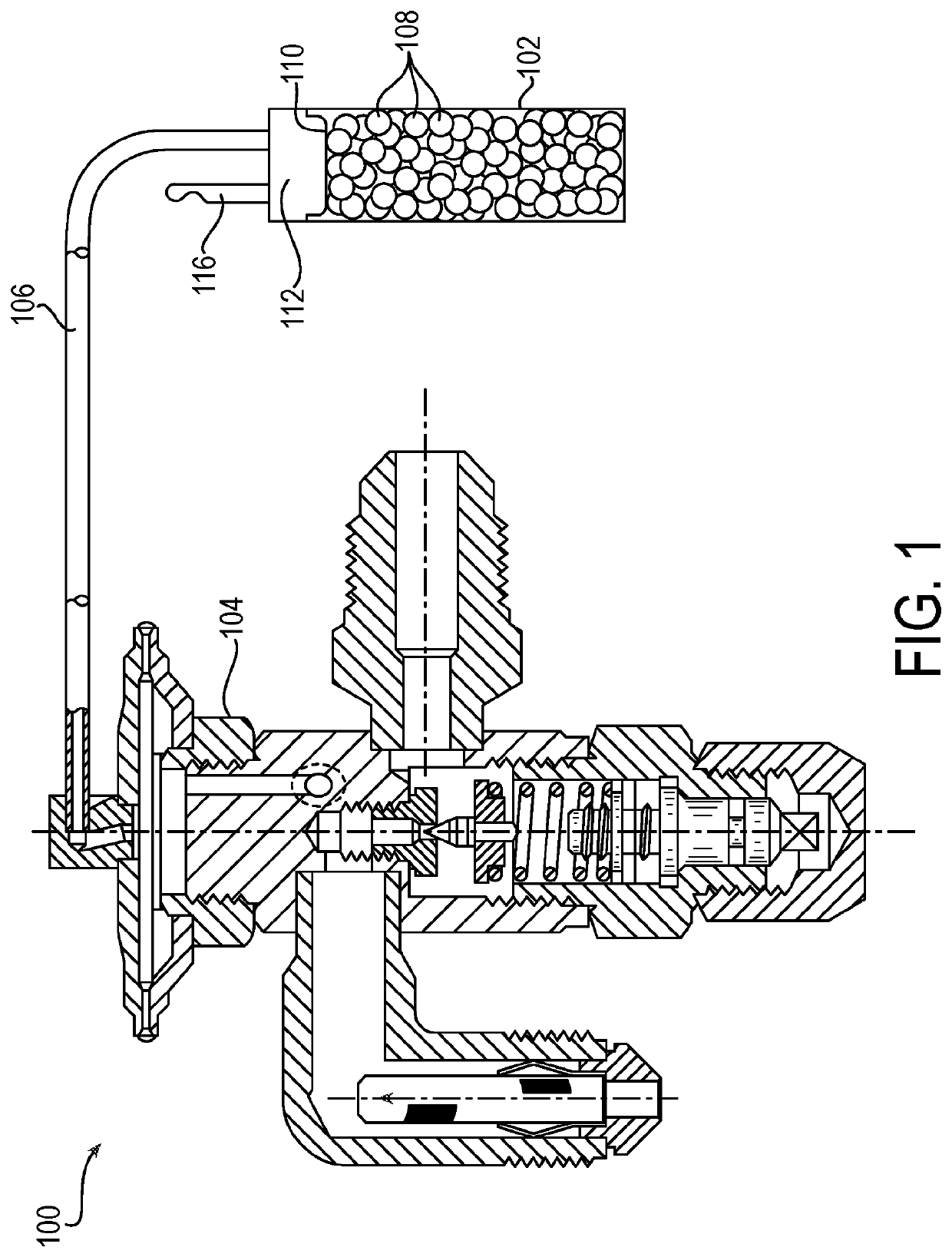
[0020]According to an aspect of the present disclosure, a refrigerant system is provided including a thermostatic expansion valve, the expansion valve including a thermal sensing bulb, the thermal sensing bulb comprising a working fluid, the working fluid sealed inside the thermal sensing bulb and in operative communication with the expansion valve; and a ballast in the thermal sensing bulb, the ballast including an alumina material.

[0021]The refrigerant system may be a refrigeration system, such as of the compressor-condenser-evaporator type. In such a system, the thermostatic expansion valve and the thermal sensing bulb operate as a throttling device for controlling the amount of the working fluid (e.g., refrigerant in gaseous and / or liquid form) injected into the system's evaporator based on the evaporator outlet temperature and pressure. The thermal sensing bulb is located in a position of the system that is selected to provide feedback information about the thermal condition of...


PUM


Abstract

A thermal sensing bulb (102) for an expansion valve (104) in a refrigerant system, the bulb containing a ballast material (108), the ballast material including alumina. More particularly, the ballast material (108) includes alpha alumina, which may be in the form of a plurality of discrete particles having a desired surface area, particle size, and/or particle size distribution.

Description

RELATED APPLICATIONS[0001]This application claims the benefit of U.S. Provisional Application No. 62 / 788,429 filed Jan. 4, 2019, which is hereby incorporated herein by reference in its entirety.FIELD OF INVENTION[0002]The present invention relates generally to ballast material for a thermostatic expansion valve as employed in refrigerant systems, particularly of the compressor-condenser-evaporator type. More particularly, the present invention relates to a ballast material including alumina which may have a particular surface area for use in such thermostatic expansion valve.BACKGROUND[0003]A refrigerant system typically includes a thermostatic expansion valve including a thermal sensing bulb, which may operate as a refrigeration and air conditioning throttling device that controls the amount of liquid refrigerant injected into the system's evaporator. The thermal sensing bulb is located in a position selected by manufacturers and / or contractors to provide feedback information about...

Claims


Application Information

Patent Timeline
IPC IPC(8): F25B41/33C01F7/02
CPCF25B41/33C01F7/02C01P2004/60F25B2600/2513C01P2004/02F25B2341/0682F25B2500/15C01P2006/12F25B41/335
Inventor BANERJEE, DEBASISLARASH, RICHARD C.SPAUNHORST, MATTHEWHUGHES, ADAM P.
Owner PARKER HANNIFIN CORP
Why Eureka
Try Eureka