
Optical measurement apparatus

a measurement apparatus and optical technology, applied in the direction of optical apparatus testing, optical radiation measurement, instruments, etc., can solve the problems of not being able to achieve the expected low-temperature condition, unable to control the temperature, and expensive test station with built-in cooling and temperature control functions for measuring optical characteristics, etc., to achieve stable low-temperature environment, reduce fabrication costs, and simplify construction

Pending Publication Date: 2021-12-09
YOUNG OPTICS
View PDF6 Cites 0 Cited by
  • Summary
  • Abstract
  • Description
  • Claims
  • Application Information

AI Technical Summary

Benefits of technology

The patent is about a cooling system that can create a stable and low-temperature environment for optical measurements. The system is cost-effective and easy to set up. The temperature can be accurately controlled by adjusting the electric currents. The system also has a defogging function to clear any condensation or frost, which helps to make accurate and stable measurements. The photosensor is placed outside the chamber, so it is not affected by the temperature of the chamber, which improves the measurement accuracy.

Problems solved by technology

However, a test station with built-in cooling and temperature control functions for measuring optical characteristics is very expensive.
Moreover, an alternate method of using a coolant to lower the temperature not only fails to control the temperature, but also takes a very long time to obtain the expected low-temperature condition that only lasts for a limited period of time.

Method used


Image

  • Optical measurement apparatus
  • Optical measurement apparatus
  • Optical measurement apparatus

Examples


Embodiment Construction

[0011]In the following detailed description of the preferred embodiments, directional terminology, such as “top,”“bottom,”“front,”“back,” etc., is used with reference to the orientation of the Figure(s) being described. The components of the invention can be positioned in a number of different orientations. As such, the directional terminology is used for purposes of illustration and is in no way limiting. Further, “First,”“Second,” etc, as used herein, are used as labels for nouns that they precede, and do not imply any type of ordering (e.g., spatial, temporal, logical, etc.).

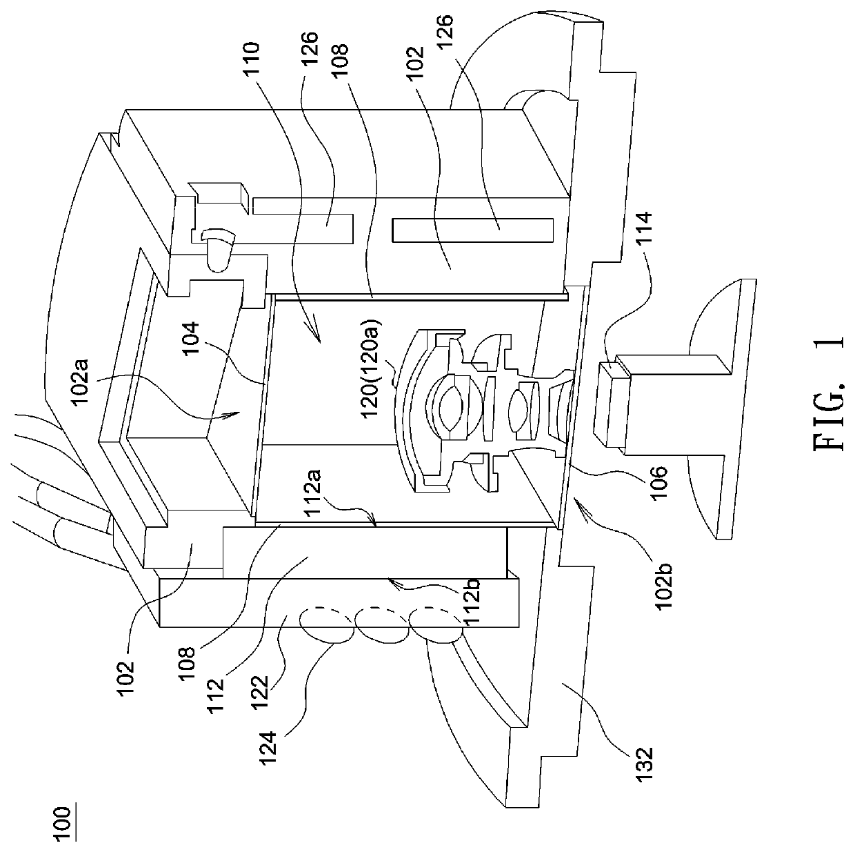
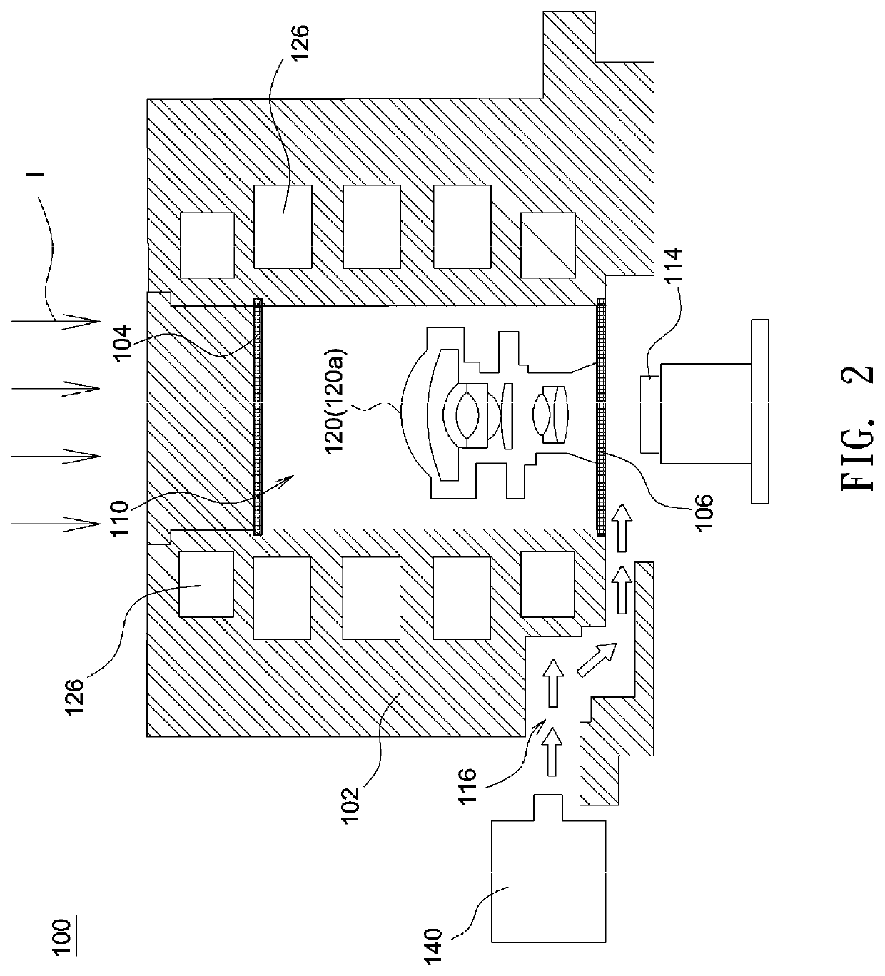
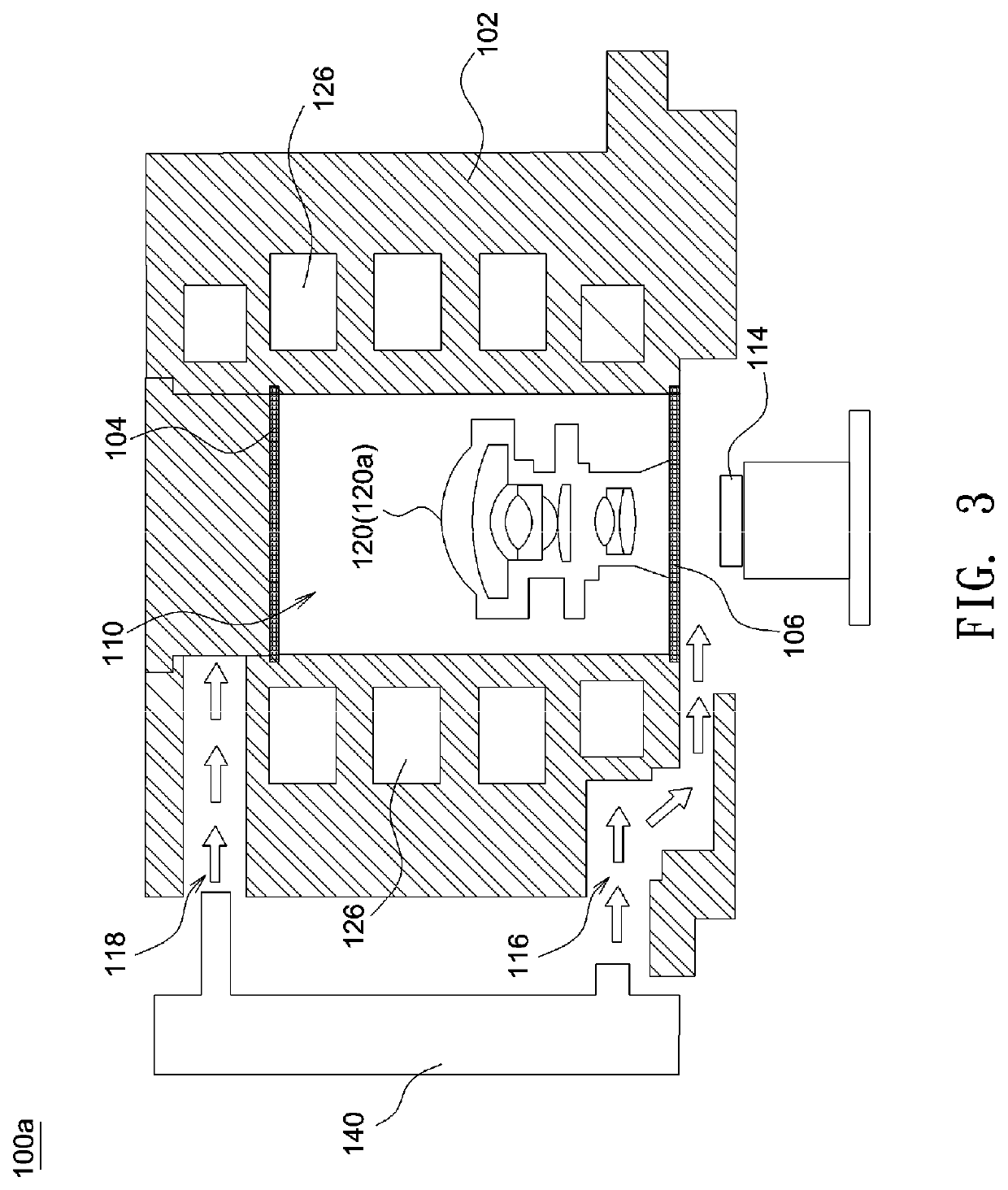
[0012]FIG. 1 and FIG. 2 respectively show a perspective view and a schematic plan view of an optical measurement apparatus according to an embodiment of the invention, where a defogging unit and a fluid-guiding structure for the optical measurement apparatus are additionally depicted in FIG. 2. As shown in FIG. 1, the optical measurement apparatus 100 may include a thermal insulation housing 102, a first ligh...


PUM


Abstract

An optical measurement apparatus includes a thermal insulation housing, a first light-transmissive plate, a second light-transmissive plate, a heat-conductive layer, a cooling source and a photosensor. The thermal insulation housing, the first light-transmissive plate and the second light-transmissive plate define a chamber. The heat-conductive layer is disposed in the chamber, the cooling source is coupled to the heat-conductive layer, and the photosensor is disposed outside the chamber and on one side of the second light-transmissive plate facing away from the first light-transmissive plate.

Description

BACKGROUND OF THE INVENTIONa. Field of the Invention[0001]The invention relates to an optical measurement apparatus.b. Description of the Related Art[0002]Nowadays, the degree to which the performance of an optical lens is affected under a low-temperature environment simulating extreme climatic conditions can be measured by modern technologies. However, a test station with built-in cooling and temperature control functions for measuring optical characteristics is very expensive. Moreover, an alternate method of using a coolant to lower the temperature not only fails to control the temperature, but also takes a very long time to obtain the expected low-temperature condition that only lasts for a limited period of time. Therefore, it would be desirable to provide an optical measurement apparatus having simplified construction, low fabrication costs, and adjustable temperature controls.[0003]The information disclosed in this “BACKGROUND OF THE INVENTION” section is only for enhancement...

Claims


Application Information

Patent Timeline
IPC IPC(8): G02B27/00G02B7/02G01J1/02
CPCG02B27/0006G01J1/0252G02B7/028G01M11/0207G01M11/0264G01M11/02
Inventor CHIU, WEI-TINGCHAN, CHU-TSUNGPARAL, SANDEEP KUMARLEE, CHIA-CHANG
Owner YOUNG OPTICS
Learn More