
Hair pulling device

a hair pulling device and hair technology, applied in hair cleaning, hair equipment, hair singing, etc., can solve the problems of large increase in production costs, and low working efficiency of existing hair pulling devices, and achieve high hair pulling efficiency and long service life.

Pending Publication Date: 2021-12-16
JIN BINGJIE
View PDF1 Cites 0 Cited by
  • Summary
  • Abstract
  • Description
  • Claims
  • Application Information

AI Technical Summary

Benefits of technology

The present invention is a hair pulling device with high efficiency and a long service life. It uses first guide raised rail sections for realizing the closing and clamping actions of the clamping mouths on the upper part of the hair clamping assembly units. This results in a high hair clamping efficiency, reliable and stable clamping force, and avoids problems of hair pulling fails due to elastic parts failure or insufficient clamping force. The device features a unit combination mode and a simplified structure, reducing production costs and facilitating repid and assembly. The design allows for multiple positioning frames and maximizes the number of hair clamping points, ensuring effective and rapid hair pulling action.

Problems solved by technology

Existing hair removal devices mainly have low working efficiency.
However, working efficiency of the device is low.
In addition, because of the structure, it is impossible to add too many sets of hair pulling assemblies along circumferences of hair pulling device assembly as the hair pulling force can be influenced and the production cost can be greatly increased.
In addition, the clamping plate assemblies are clamped and opened by the springs which can easily fail after long time of use, which can surely lead to failure of the hair removal device.

Method used


Image

  • Hair pulling device
  • Hair pulling device
  • Hair pulling device

Examples


Embodiment Construction

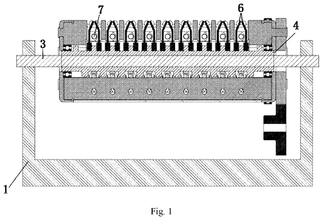
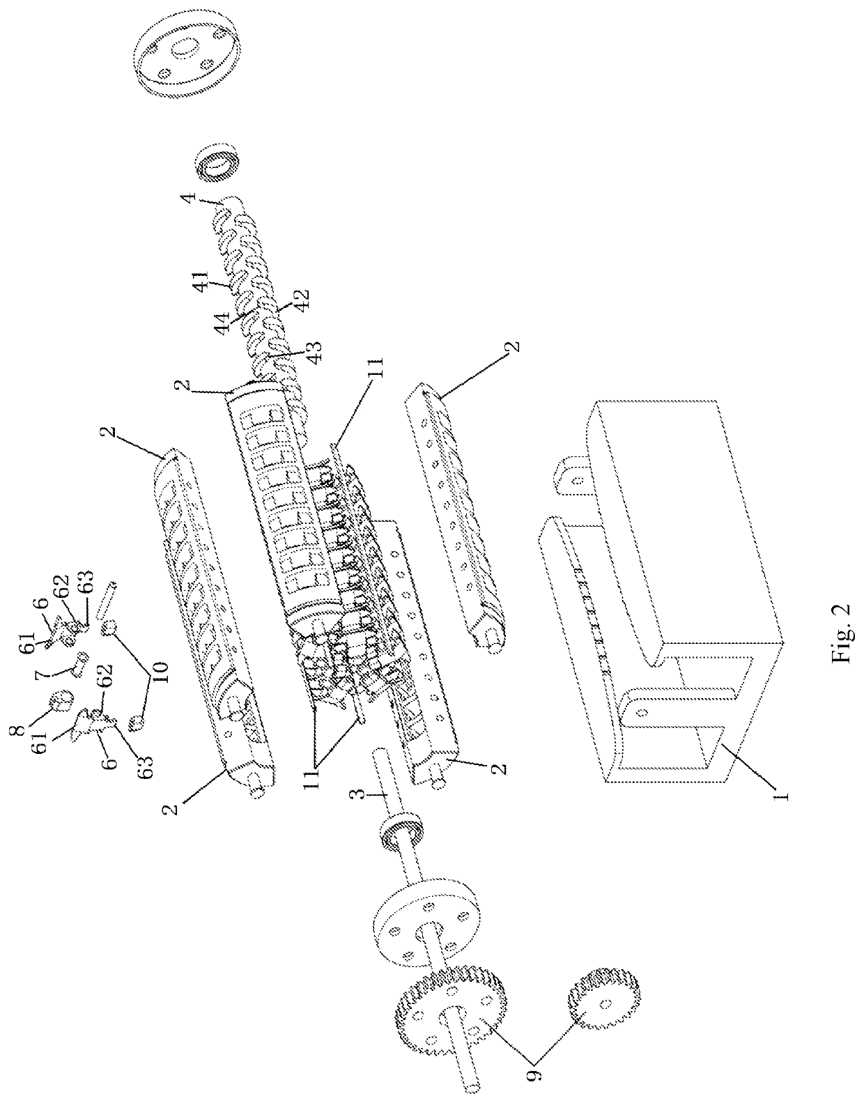
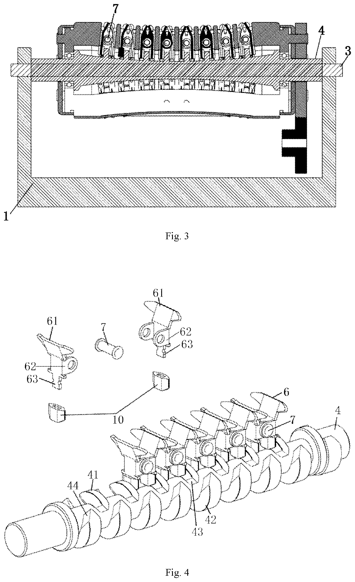
[0020]As shown in FIG. 1 and FIG. 2, in a first embodiment of a hair pulling device of the present invention, the hair pulling device includes a machine body which is provided with a hair clamping support and a driving device; a fixation shaft 3 which is fixed and non-rotary as well as five positioning frames 2 which are driven by the driving device to rotate around the fixation shaft 3 are disposed on the hair clamping support 1; and the five positioning frames are disposed in an equally divided and surrounded manner and are installed and connected at intervals by lubricating bars 11, so as to enhance hair pulling comfort. The driving device in the present embodiment drives an end cap 5 and each positioning frame connected to the end cap 5 to rotate by a gear set 9; a plurality of positioning holes are arranged and formed in the positioning frame; and a plurality of groups of hair clamping assembly units which are rotated with the positioning frames 2 are disposed, along an axial d...


PUM


Abstract

A hair pulling device includes a machine body which is provided with a hair clamping support (1) and a driving device. A fixation shaft (3) which is fixed and non-rotary as well as a plurality of positioning frames (2) which are driven by the driving device to rotate around the fixation shaft (3) are disposed on the hair clamping support (1); a plurality of groups of hair clamping assembly units which are rotated with the positioning frames (2) are disposed, along an axial direction of the fixation shaft (3), on the positioning frames (2); the fixation shaft (3) is fixedly sleeved by a positioning shaft (4); The hair pulling device has high hair clamping efficiency and reliable and stable clamping force, and avoids the problems that hair pulling fails due to failure of an elastic part or hair pulling fails due to insufficient clamping force.

Description

CROSS-REFERENCE TO RELATED APPLICATIONS[0001]This application is a continuation of International Patent Application No. PCT / CN2019 / 116603, filed on Nov. 8, 2019, which claims the benefit of priority from Chinese Patent Application No. 201910525469.X, filed on Jun. 18, 2019. The content of the aforementioned applications, including any intervening amendments thereto, is incorporated herein by reference in its entirety.TECHNICAL FIELD[0002]The present invention relates to a hair removal device, and in particular to an electric hair pulling device.BACKGROUND OF THE PRESENT INVENTION[0003]A hair removal device is generally used for pulling body hair. Existing hair removal devices mainly have low working efficiency. An existing electric hair pulling device mainly includes a hair pulling device assembly and a motor driving device; the hair pulling device assembly includes a hair pulling support, side supports, a middle shaft, a cylindrical cam, a cylindrical roller assembly, clamping plat...

Claims


Application Information

Patent Timeline
IPC IPC(8): A45D26/00
CPCA45D26/0033A45D2026/008
Inventor JIN, BINGJIE
Owner JIN BINGJIE
Learn More