Optical switch module and control method thereof

Active Publication Date: 2021-12-16
ASUSTEK COMPUTER INC
View PDF1 Cites 0 Cited by
  • Summary
  • Abstract
  • Description
  • Claims
  • Application Information

AI Technical Summary

Benefits of technology

[0013]The optical switch module and the control method thereof provided in the disclosure effectively shorten the preparation time of the light receiving unit and increase t

Problems solved by technology

Besides, the light-emitting diode stays on for a long time and causes high power consumption.
Therefor

Method used


Image

  • Optical switch module and control method thereof
  • Optical switch module and control method thereof
  • Optical switch module and control method thereof

Examples


Example

[0017]Embodiments of the disclosure are described in further detail below with reference to the accompanying drawings. The advantages and features of the disclosure are described more clearly according to the following description and claims. It is to be noted that all of the drawings use very simplified forms and imprecise proportions, which are only used for assisting in conveniently and clearly explaining the objective of the embodiments of the disclosure.

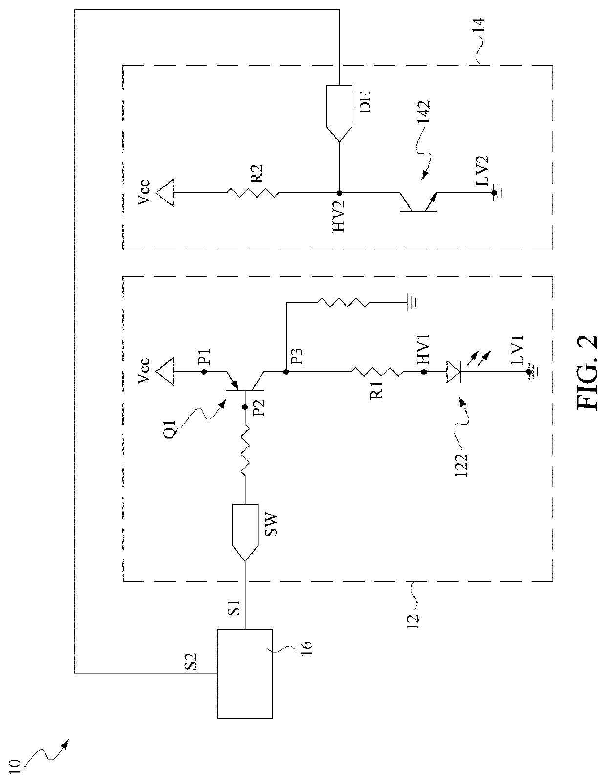
[0018]FIG. 2 is a schematic block diagram of an optical switch module according to an embodiment of the disclosure. The optical switch module 10 is applied to an input device, such as a keyboard or a mouse.

[0019]As shown in the figure, the optical switch module 10 includes a light generation circuit 12, a light receiving circuit 14, and a control unit 16.

[0020]The light generation circuit 12 includes a light generation unit 122 and a control end SW. The light generation unit 122 generates light according to a control signal S1 f...


PUM


Abstract

An optical switch module including a light generation circuit, a light receiving circuit, and a control unit is provided. The light generation circuit includes a light generation unit and a control end, and generates light according to a control signal from the control end. The light receiving circuit includes a light receiving unit and a signal reading end, and is configured to receive light to generate a detection signal at the signal reading end. The control unit is configured to generate the control signal and receive the detection signal. The control unit further selectively configures the signal reading end in an input mode or an output mode. Before the control unit configures the signal reading end in the input mode to read the detection signal, the control unit configures the signal reading end in the output mode to pull up a potential of the light receiving unit.

Description

CROSS-REFERENCE TO RELATED APPLICATION[0001]This application claims the priority benefit of Chinese Application Serial No. 202010523502.8, filed on Jun. 10, 2020. The entirety of the above-mentioned patent application is hereby incorporated by reference herein and made a part of specification.BACKGROUND OF THE INVENTIONField of the Invention[0002]The disclosure relates to an input device, and in particular, to an optical switch module applied to an input device and a control method thereof.Description of the Related Art[0003]The optical switch is a micro-switch technology developed from the conventional mechanical keyboard. In the technology, a light-emitting diode and an infrared optical sensor replace a metallic elastic piece in the structure of a conventional mechanical switch. The two ways that an open circuit and a closed circuit, are formed by applying the light sensing principle to trigger a key signal. An optical switch keyboard has advantages such as strong interference res...

Claims


Application Information

Patent Timeline
IPC IPC(8): H03K17/969H03K17/94G06F3/02
CPCH03K17/969G06F3/02H03K17/943H01H13/85G06F3/0202
Inventor LIN, KUO-ENLIN, CHIH-YUANCHOU, SHIH-HUNGCAI, XIN-HANHSIEH, I-TING
Owner ASUSTEK COMPUTER INC
Why Eureka
Try Eureka