
Micro light emitting diode display panel, method for fabricating same, and display device

a light-emitting diode and display panel technology, applied in the field of display technology, can solve the problems of affecting the display effect, shifting the threshold voltage, and large light leakage current, so as to reduce the influence of light emitted, reduce the threshold voltage (vth), and reduce the effect of light leakage curren

Active Publication Date: 2021-12-23
SHENZHEN CHINA STAR OPTOELECTRONICS TECH CO LTD
View PDF0 Cites 2 Cited by
  • Summary
  • Abstract
  • Description
  • Claims
  • Application Information

AI Technical Summary

Benefits of technology

The present invention provides a micro light emitting diode display panel with improved display quality and reduced light leakage current. The panel includes a thin film transistor and a light shielding layer that blocks the light emitted by the micro light emitting diode from affecting the thin film transistor. This results in reduced shift in threshold voltage and improved contrast between bright and dark. Overall, the technical problem of the current micro light emitting diode display panel is solved.

Problems solved by technology

Because light emitted by a micro light emitting diode is omni-directional, a thin film transistor (TFT) in a thin film transistor array is subjected to short-wavelength light emitted by the micro-light-emitting diode to cause a shift in threshold voltage (Vth), thereby causing a light leakage current to become large and affecting the display effect.
That is, the current micro light emitting diode display panel has a technical problem that the light emitted by the micro light emitting diode causes the shift of the threshold voltage of the thin film transistor, and needs improvement.

Method used


Image

  • Micro light emitting diode display panel, method for fabricating same, and display device
  • Micro light emitting diode display panel, method for fabricating same, and display device
  • Micro light emitting diode display panel, method for fabricating same, and display device

Examples


Embodiment Construction

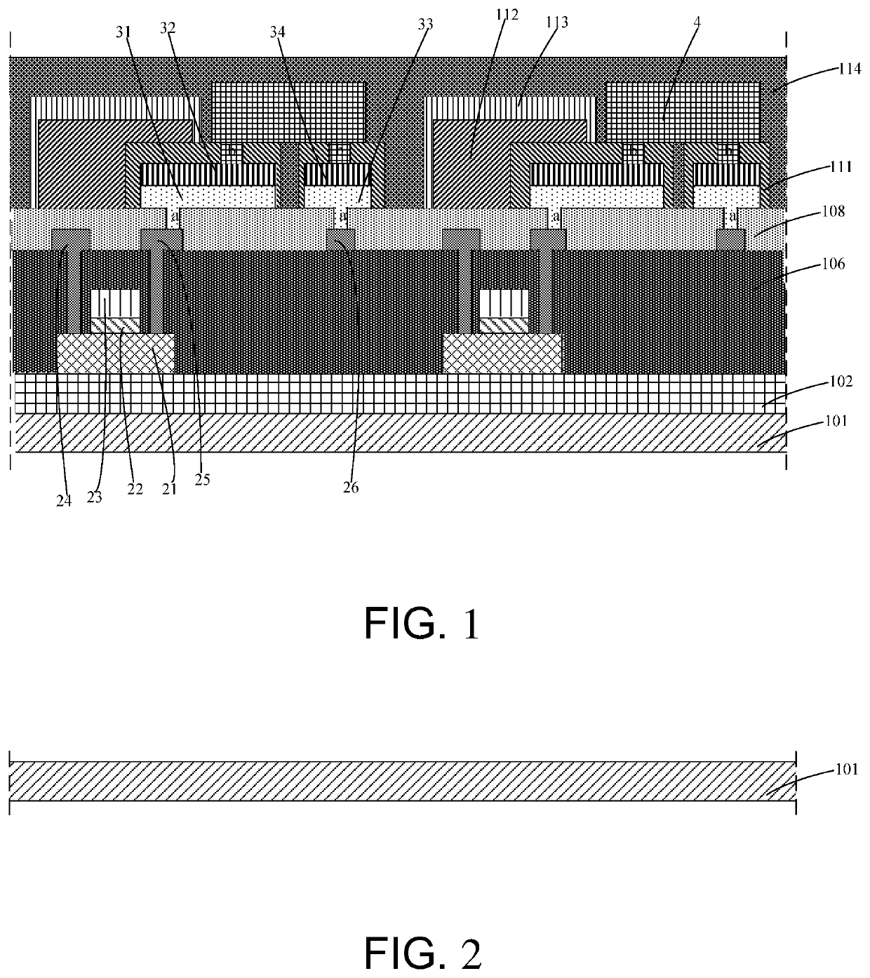
[0063]The following description of various embodiments of the present disclosure with reference to the accompanying drawings is used to illustrate specific embodiments that can be practiced. Directional terms mentioned in the present disclosure, such as “above”, “below”, “front”, “rear”, “left”, “right”, “inside”, “outside”, “side”, are merely used to indicate the direction of the accompanying drawings. Therefore, the directional terms are used for illustrating and understanding the present disclosure rather than limiting the present disclosure. In the figures, elements with similar structure are indicated by the same reference numerals.

[0064]The embodiments of the present disclosure can solve the technical problem of the current micro light emitting diode display panel that the light emitted by the micro light emitting diode causes the shift of the threshold voltage of the thin film transistor.

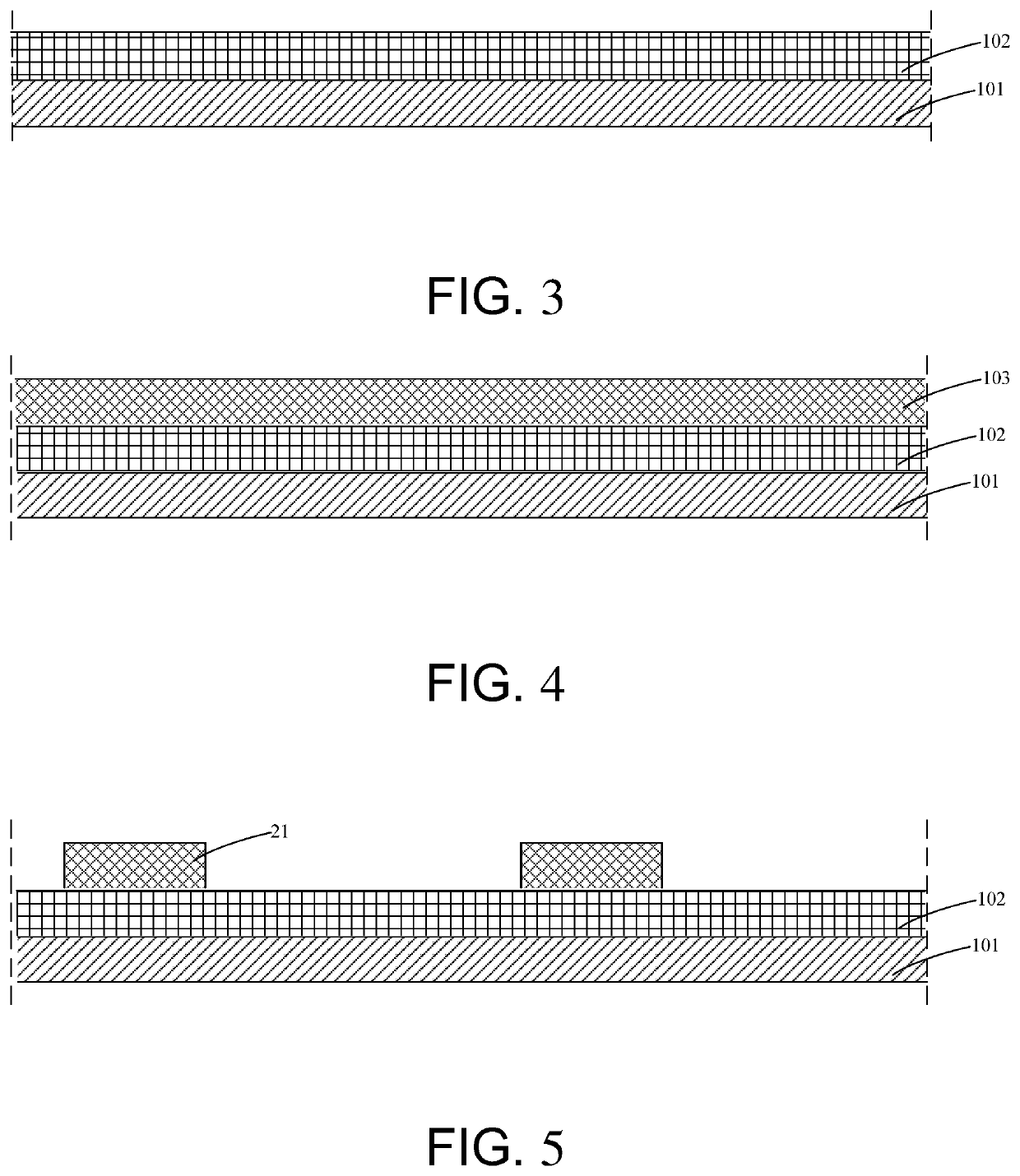
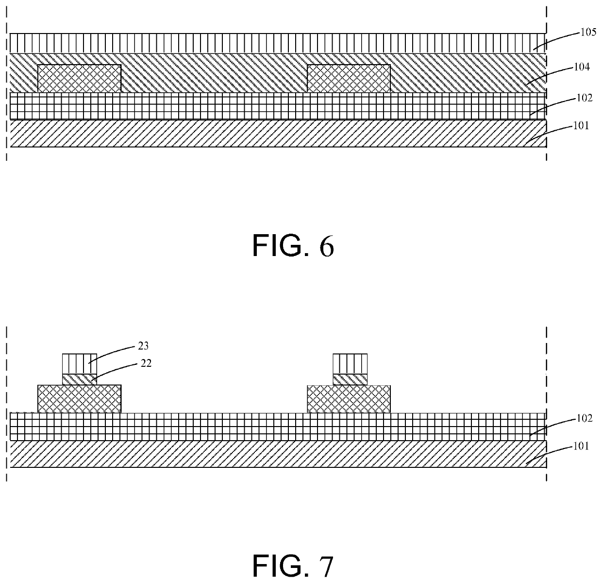
[0065]As shown in FIG. 1, the present disclosure provides a micro light emitting diode di...


PUM

PropertyMeasurementUnit
densityaaaaaaaaaa
threshold voltageaaaaaaaaaa
structureaaaaaaaaaa

Abstract

The present disclosure provides a micro light emitting diode display panel, a method for fabricating the same, and a display device comprising the same. The micro light emitting diode display panel includes an active layer, a gate insulating layer, a gate electrode, a source electrode, a drain electrode, a pixel electrode, a micro light emitting diode, and a gate insulating layer covering the active layer, the gate insulating layer, the gate electrode, the source electrode, and the drain electrode. The light shielding layer blocks light emitted by the micro light emitting diode from being incident on the thin film transistor, thereby reducing influence of the light emitted by the micro light emitting diode light on the thin film transistor.

Description

FIELD OF INVENTION[0001]The present disclosure relates to a field of display technology, and particularly to a micro light emitting diode display panel, a method for fabricating the same, and a display device comprising the same.BACKGROUND[0002]A current micro light emitting diode (micro LED) display panel is a self-emitting display device that displays an image using a high-density micro light-emitting diode array integrated on a substrate as display pixels.[0003]Because light emitted by a micro light emitting diode is omni-directional, a thin film transistor (TFT) in a thin film transistor array is subjected to short-wavelength light emitted by the micro-light-emitting diode to cause a shift in threshold voltage (Vth), thereby causing a light leakage current to become large and affecting the display effect.[0004]That is, the current micro light emitting diode display panel has a technical problem that the light emitted by the micro light emitting diode causes the shift of the thre...

Claims


Application Information

Patent Timeline
Patent Type & Authority Applications(United States)
IPC IPC(8): H01L25/075H01L27/12H01L29/786H01L33/62
CPCH01L25/0753H01L27/1214H01L2933/0066H01L33/62H01L29/78633H01L29/0684H01L27/1259H01L25/167H01L33/58H01L27/1248
Inventor ZHANG, WEILU, MACAILIU, MINGGANGHSU, CHUNCHELEE, CHIAYU
Owner SHENZHEN CHINA STAR OPTOELECTRONICS TECH CO LTD
Learn More