Control apparatus, image pickup apparatus, control method, and storage medium
- Summary
- Abstract
- Description
- Claims
- Application Information
AI Technical Summary
Benefits of technology
Problems solved by technology
Method used
Image

Examples
first embodiment
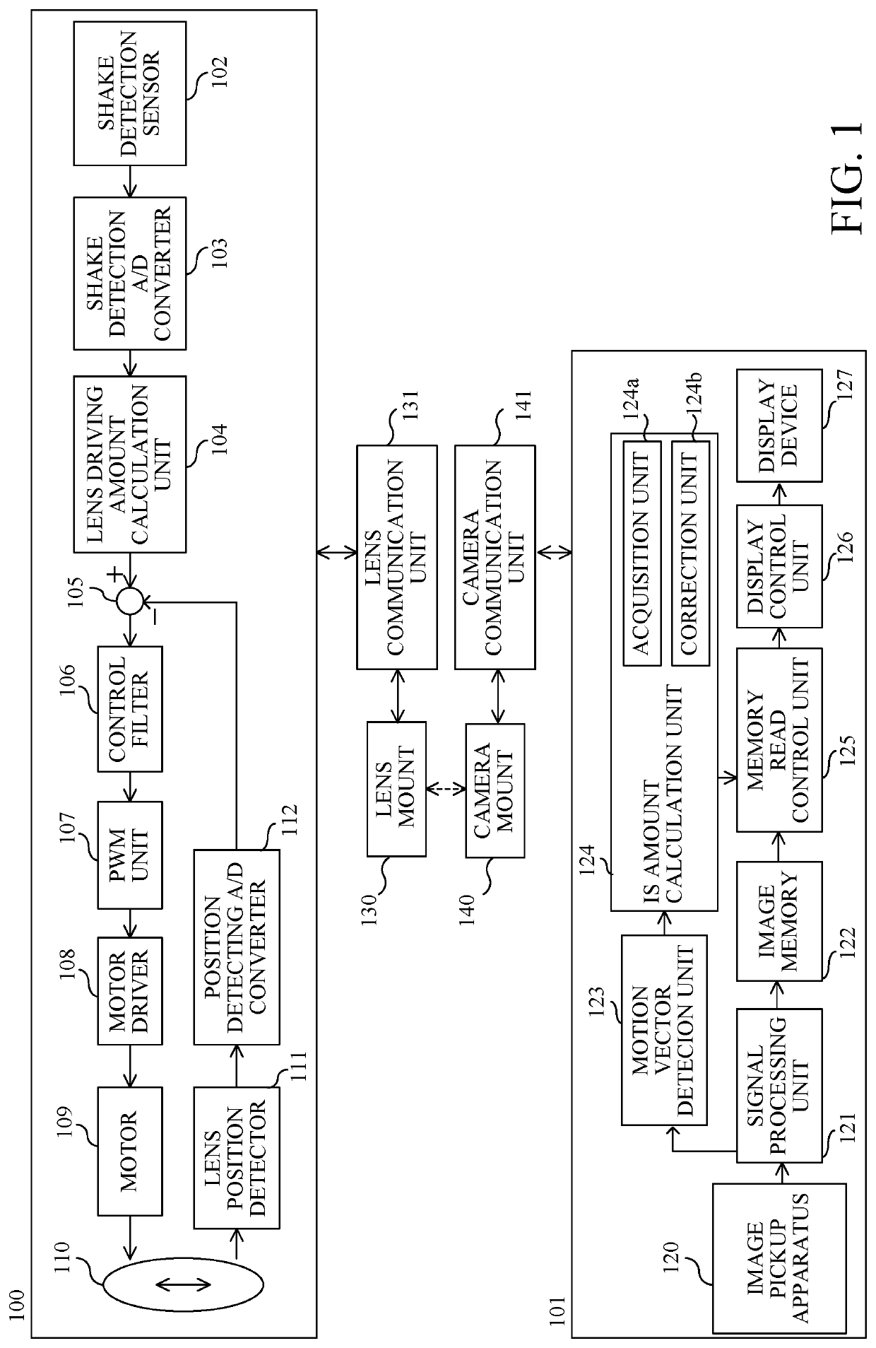
[0018]Referring now to FIG. 1, a description will be given of a configuration and operation of an image pickup apparatus according to a first embodiment of the disclosure. FIG. 1 is a block diagram of an image pickup apparatus (video camera) 10 according to this embodiment. The image pickup apparatus 10 includes a camera body 101 and a lens unit 100 that is attachable to and detachable from the camera body 101. However, this embodiment is not limited to this example, and is applicable to an image pickup apparatus in which the camera body and the lens unit are integrated with each other.
[0019]The lens unit 100 is connected to the camera body 101 via a lens mount 130 and a camera mount 140. The lens mount 130 and the camera mount 140 each have an electrical connection terminal, and can communicate data between the lens unit 100 and the camera body 101 via a lens communication unit 131 and a camera communication unit (communication unit) 141.
[0020]A description will now be given of an ...
second embodiment
[0048]Next follows a description of a second embodiment according to the disclosure. The first embodiment changes the threshold (reference shutter speed) of the shutter speed for correcting the EIS gain based on the correction stage number information (correction performance) of the OIS. On the other hand, this embodiment changes the correction amount (change amount) of the EIS gain based on the correction stage number information of the OIS. Thereby, similar to the first embodiment, this embodiment can obtain a good IS effect while avoiding the object blur caused by the accumulated blur. The configuration and operation of the image pickup apparatus in this embodiment are the same as those of the image pickup apparatus 10 in the first embodiment described with reference to FIG. 1, and thus a description thereof will be omitted.
[0049]FIG. 5 illustrates a relationship between the shutter speed and the correction gain (EIS gain) of the EIS relative to the correction stage number inform...
third embodiment
[0060]Next follows a description of a third embodiment according to the disclosure. The first and second embodiments change the threshold of the shutter speed for correcting the EIS gain or the correction amount of the EIS gain based on the correction stage number information of the OIS. On the other hand, this embodiment detects, as information on the correction performance of the OIS by the correction optical system 110, the remaining correction amount of the OIS, and changes the correction amount of the EIS gain in the low shutter speed range based on the remaining correction amount. Thereby, this embodiment can obtain a good IS effect while avoiding the object blur caused by the accumulated blur. The configuration and operation of the image pickup apparatus according to this embodiment are the same as those of the image pickup apparatus 10 in the first embodiment described with reference to FIG. 1, and thus a description thereof will be omitted.
[0061]FIGS. 7A and 7B illustrate a...
PUM
 Abstract
Description
Claims
Application Information
 - Generate Ideas
- Intellectual Property
- Life Sciences
- Materials
- Tech Scout
- Unparalleled Data Quality
- Higher Quality Content
- 60% Fewer Hallucinations
Browse by: Latest US Patents, China's latest patents, Technical Efficacy Thesaurus, Application Domain, Technology Topic, Popular Technical Reports.
© 2025 PatSnap. All rights reserved.Legal|Privacy policy|Modern Slavery Act Transparency Statement|Sitemap|About US| Contact US: help@patsnap.com