Eureka AIR delivers breakthrough ideas for toughest innovation challenges, trusted by R&D personnel around the world.

Double-sided turning film

a turning film and double-sided technology, applied in the field of display illumination, can solve the problems of affecting dimensional accuracy and challenging lamination solutions, and achieve the effect of improving the level of on-axis brightness and compact solution

Inactive Publication Date: 2008-10-23
SKC HAAS DISPLAY FILMS CO LTD
View PDF16 Cites 46 Cited by
  • Summary
  • Abstract
  • Description
  • Claims
  • Application Information

AI Technical Summary

Benefits of technology

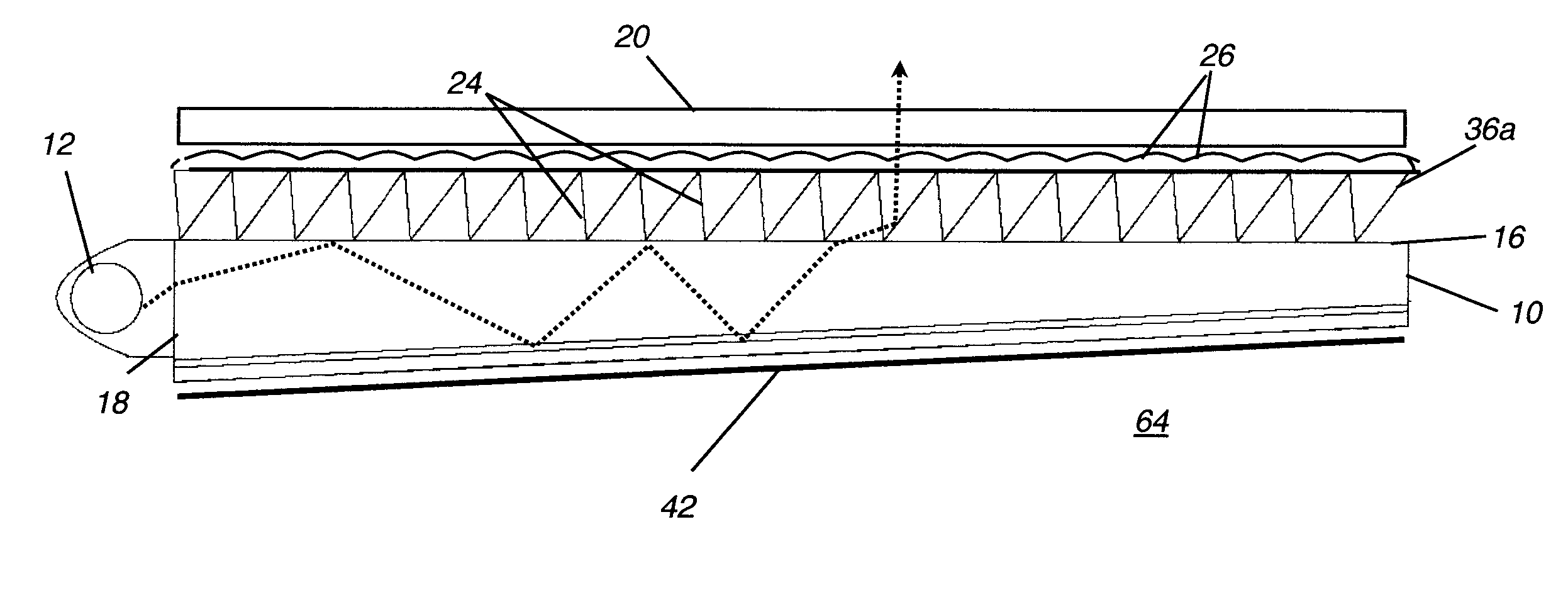
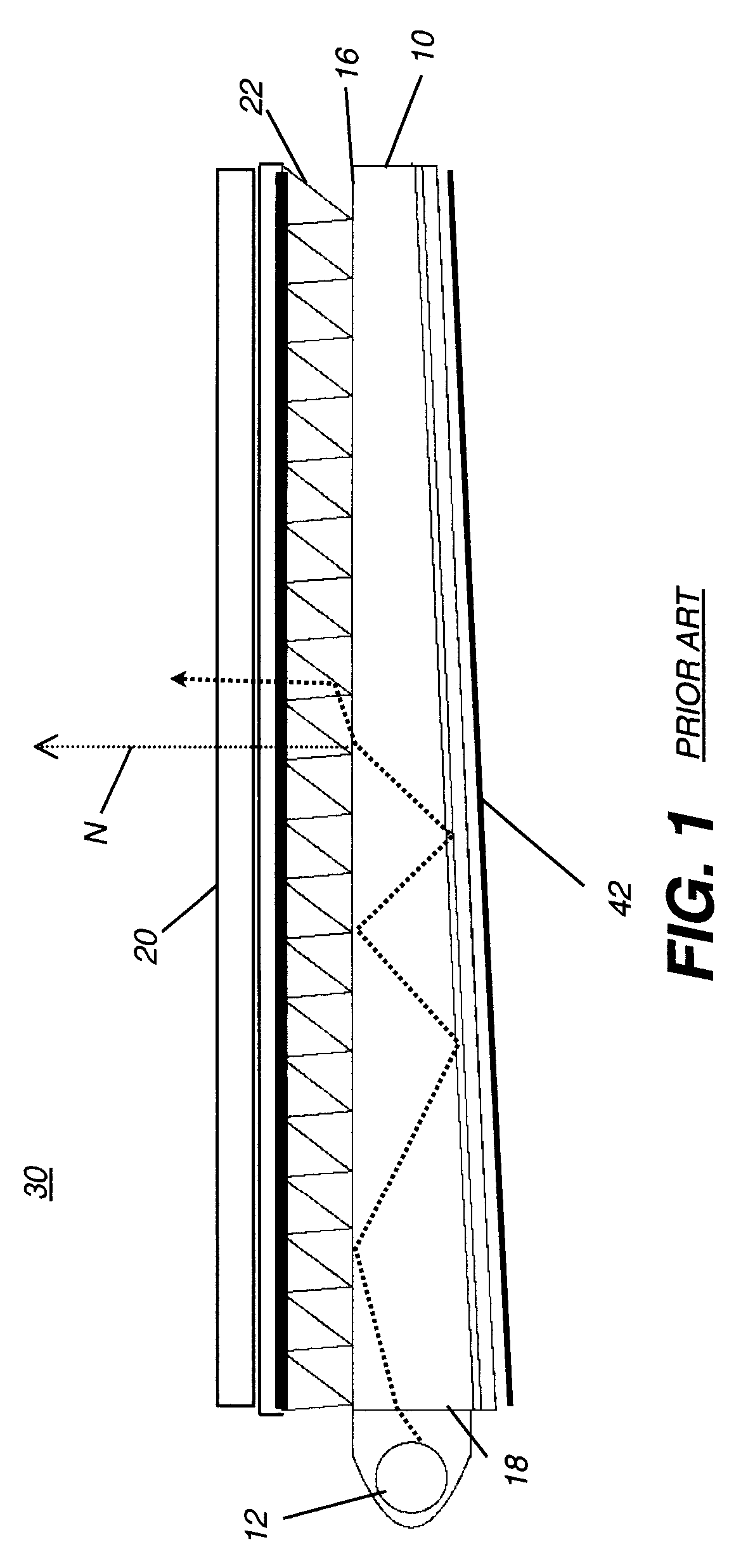
[0017]It is an advantage of the present invention that it can provide a more compact solution for displays than conventional brightness enhancement films provide, and combines functions of light collimation and light redirection from a single component.

Problems solved by technology

Each of these conventional approaches, however, presents some problems, particularly where it is necessary to obtain precise registration of structures formed on opposite sides of the optical film.
Lamination solutions can prove to be challenging, since the heat generated during lamination transfer can impact dimensional accuracy for the plastic sheet materials that are used.

Method used


Image

  • Double-sided turning film
  • Double-sided turning film
  • Double-sided turning film

Examples


Embodiment Construction

[0055]The present description is directed in particular to elements forming part of, or cooperating more directly with, apparatus in accordance with the invention. It is to be understood that elements not specifically shown or described may take various forms well known to those skilled in the art.

[0056]The invention is represented in at least the following modes:

[0057]I. a backlight device for a display comprising (1) a side-lit light source, (2) a light guide plate, and (3) a turning film comprising melt-extrudable and thermo-formable polymeric material, the turning film comprising prismatic structures on the light entry surface of the film and lenticular elements on the light exit surface of the film, wherein:

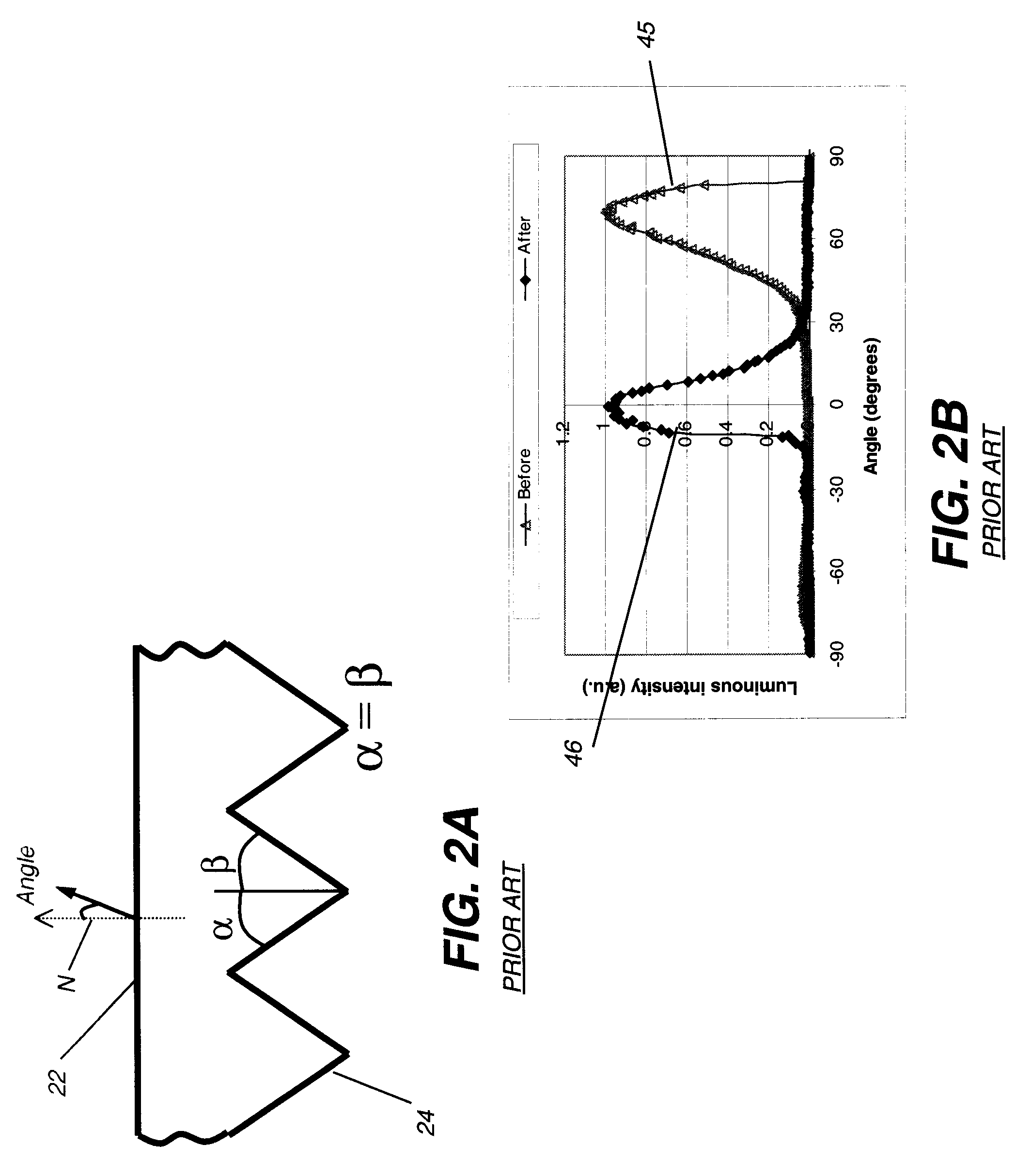
[0058](a) the prismatic structures are characterized by an average apex angle (α+β) and an average pitch (Q);

[0059](b) the lenticular elements are characterized by an average pitch (P) and an average radius of curvature (R); and

[0060](c) the prismatic structures and lenticul...


PUM

PropertyMeasurementUnit
angleaaaaaaaaaa
exit angleaaaaaaaaaa
peak half-angleaaaaaaaaaa

Abstract

A backlight device for a display comprising (1) a side-lit light source, (2) a light guide plate and (3) a turning film comprising a light entry and a light exit surface comprising lenticular elements on the exit surface and prismatic structures on the entry surface, wherein the average values of the parameters of the features and the thickness of the film are selected to provide a peak output angle of ±10° from normal to the light exit surface of the light guide plate and an optical gain of at least 1.25. Also disclosed are methods of making the turning film and a display incorporating the backlight.

Description

CROSS REFERENCE TO RELATED APPLICATIONS[0001]Reference is made to commonly-assigned copending U.S. Patent Application Publication No. US20044786858A, filed Feb. 25, 2004, entitled RADIAL CONTACT EXTRUSION DIE, by Bomba et al., the disclosure of which is incorporated herein.FIELD OF THE INVENTION[0002]This invention generally relates to display illumination for enhancing luminous intensity from a turning film and more particularly from a turning film having microstructures on both surfaces.BACKGROUND OF THE INVENTION[0003]Portable Liquid Crystal Displays (LCDs) that are used for laptop computers and other personal computing and communication devices require a backlighting unit that is compact and relatively efficient. In many single-viewer applications of LCD displays, only a narrow viewing angle is required. By providing illumination directed primarily toward the viewer, that is, in a normal direction, an efficient backlighting unit meets this need and requires less energy, thus con...

Claims


Application Information

Patent Timeline
Patent Type & Authority Applications(United States)
IPC IPC(8): F21V5/02B29D11/00F21V8/00
CPCB29D11/00663G02B6/0053G02B6/0065G02B5/04G02B5/02G02F1/1335
Inventor MI, XIANG-DONGBOMBA, RICHARD D.BOURDELAIS, ROBERT P.FERRANTI, MICHAEL L.GREENER, JEHUDAHARASTA, LOUIS P.LEI, HERONGMEISSNER, STEPHEN C.NEERBASCH, STEVEN J.WALTON, ROBERT L.PALMERI, JOHN M.ISHIKAWA, TOMOHIRO
Owner SKC HAAS DISPLAY FILMS CO LTD
Why Eureka
Eureka Blog
Learn More