External cavity tunable compact Mid-IR laser

a compact, infrared technology, applied in the direction of lasers, lasers, semiconductor lasers, etc., can solve the problems of affecting the development of mir laser devices, affecting the actual application of mir lasers, and limiting the auger recombination, so as to achieve effective cooling, avoid moisture, and facilitate use

US7535936B2Active Publication Date: 2009-05-19DAYLIGHT SOLUTIONS
36 Cites 46 Cited by

Patent Information

Authority / Receiving Office
US · United States
Patent Type
Patents(United States)
Current Assignee / Owner
Publication Date
2009-05-19

Smart Images

  • Figure 1
    Figure 1
  • Figure 2
    Figure 2
  • Figure 3
    Figure 3
Patent Text Reader

Abstract

A compact mid-IR laser device utilizes an external cavity to tune the laser. The external cavity may employ a Littrow or Littman cavity arrangement. In the Littrow cavity arrangement, a filter, such as a grating, is rotated to provide wavelength gain medium selectivity. In the Littman cavity arrangement, a reflector is rotated to provide tuning. A quantum cascade laser gain medium provides mid-IR frequencies suitable for use in molecular detection by signature absorption spectra. The compact nature of the device is obtained owing to an efficient heat transfer structure, the use of a small diameter aspheric lens for both the output lens and the external cavity lens and a monolithic assembly structure to hold the optical elements in a fixed position relative to one another. The compact housing size may be approximately 20 cm×20 cm×20 cm or less. Efficient heat transfer is achieved using a thermoelectric cooler TEC combined with a high thermal conductivity heat spreader onto which the quantum cascade laser gain medium is thermally coupled. The heat spreader not only serves to dissipate heat and conduct same to the TEC, but also serves as an optical platform to secure the optical elements within the housing in a fixed relationship relative on one another. The small diameter aspheric output and external cavity lens each may have a diameter of 10 mm or less and each lens is positioned to provided a collimated beam output from the quantum cascade laser gain medium. The housing is hermetically sealed to provide a rugged, light weight portable MIR laser source.
Need to check novelty before this filing date? Find Prior Art

Description

BACKGROUND OF THE INVENTION

[0001] 1. Field of the Invention

[0002] Embodiments of the invention relate to a compact Mid-Infrared (MIR) laser device which is tunable utilizing an external cavity. The laser device finds applications in many fields such as, molecular detection and imaging instruments for use in medical diagnostics, pollution monitoring, leak detection, analytical instruments, homeland security and industrial process control. Embodiments of the invention are also applicable to the detection of molecules found in human breath; such molecules correlate to existing health problems such as asthma, kidney disorders and renal failure.

[0003] 2. Description of Related Art

[0004] MIR lasers of interest herein may be defined as lasers having a laser output wavelength in the range of approximately 3-12 μ / m (3333−833 cm−1). More broadly, however, “MIR” may be defined as wavelengths within a range of 3-30 μm. The far-IR is generally considered 30-300 μm, whereas the near IR is generally c...

Examples

Embodiment Construction

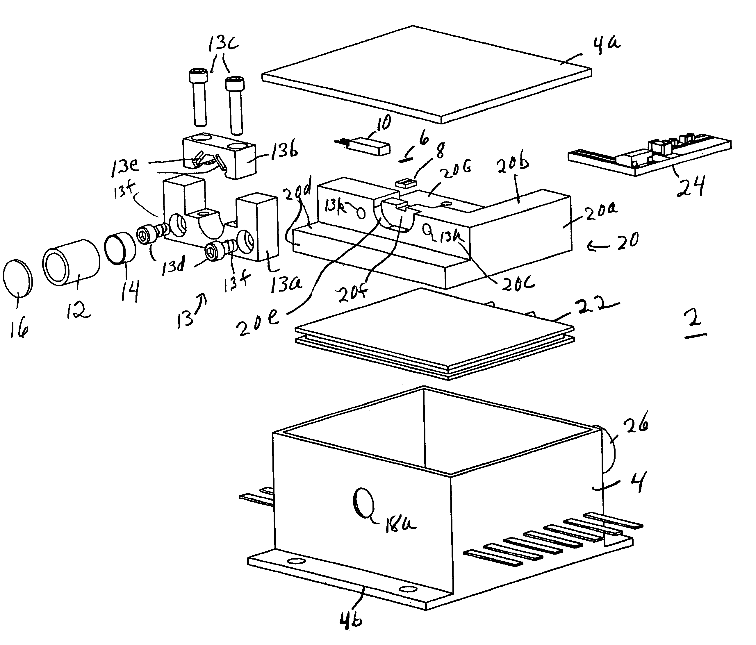
[0072]Embodiments of the invention expand upon the basic description of the MIR laser set forth above and forming part of the above referenced co-pending application which is incorporated herein in its entirety by reference. Common elements are identified by the same reference numeral throughout. The laser gain medium 6 utilized in FIGS. 1-5 is now replaced with a quantum cascade laser gain medium 6a which has an anti-reflective coating on the side of the laser chip facing the external cavity so that the wavelength dependent filter of the external cavity now serves as the fully or partially reflecting mirror for the laser.

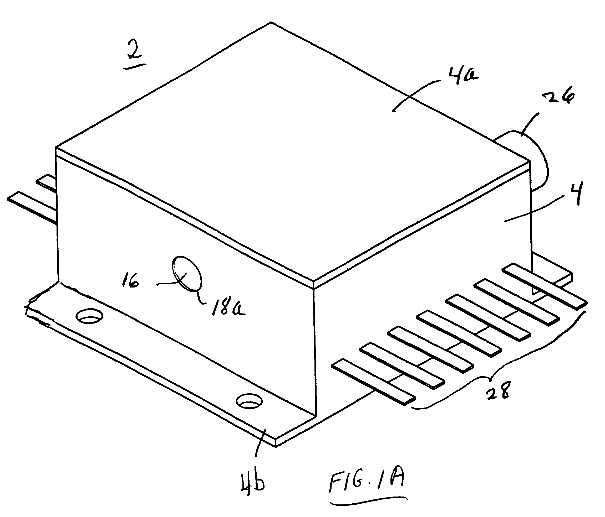
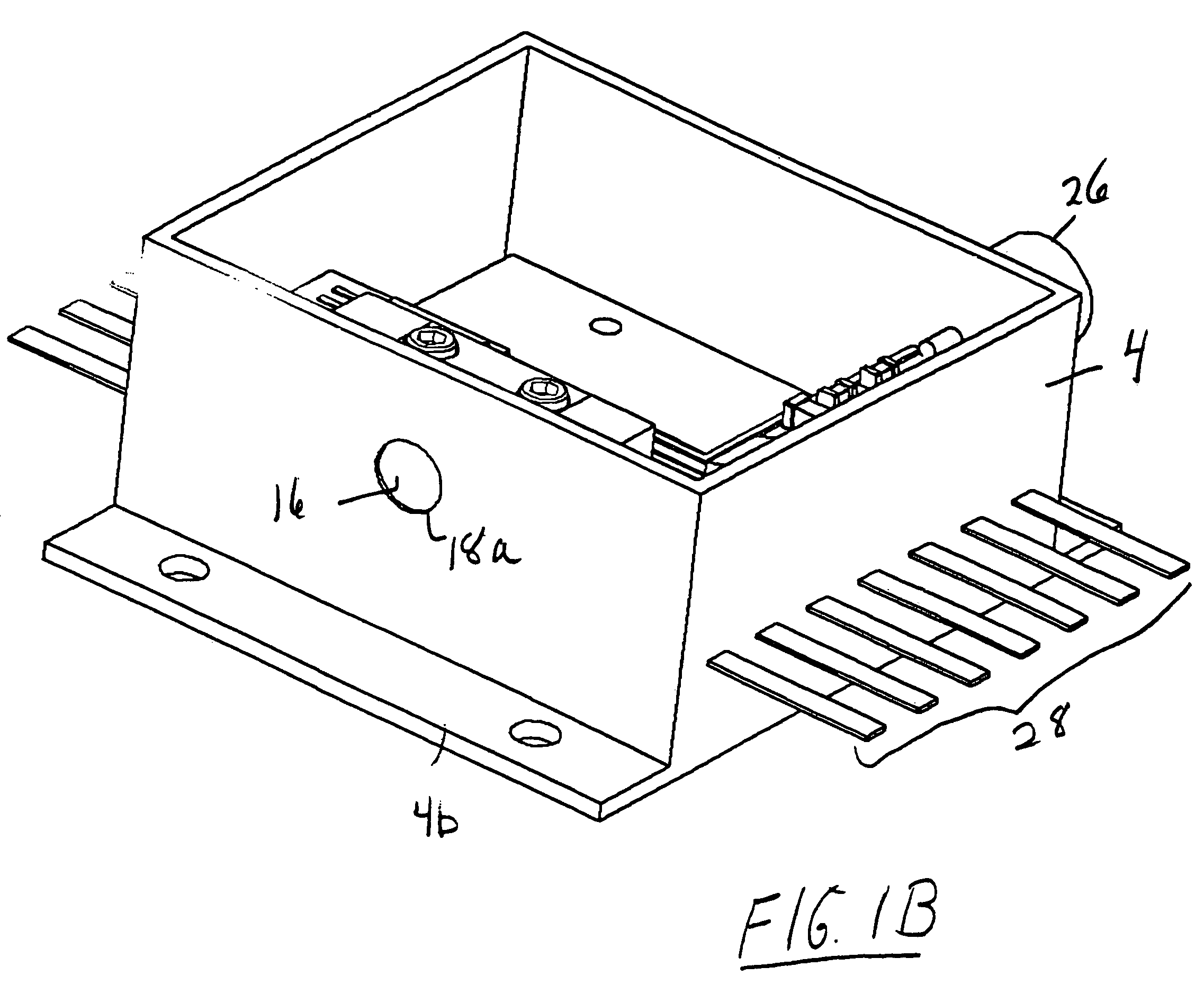
[0073]Embodiments of the invention may be seen in FIGS. 6-9. FIG. 6 shows a perspective view of the MIR laser 2, and FIGS. 7A and 7B show exploded perspective views similar to that of FIGS. 2A and 2B. FIG. 8 shows a plan view of an assembled external cavity tunable MIR laser with the top cover plate 4a removed to reveal the interior. FIG. 9A shows a cross section o...