Beam-forming apparatus and method using a spatial interpolation based on regular spatial sampling

a technology of spatial interpolation and beam-forming apparatus, applied in antennas, multi-channel direction-finding systems using radio waves, radio wave direction/deviation determination systems, etc., can solve problems such as severe interference, fading dips, and adaptive beam-forming generally only being accomplished, so as to reduce the complexity of channel estimation

Active Publication Date: 2006-11-02
SAMSUNG ELECTRONICS CO LTD
View PDF5 Cites 46 Cited by
  • Summary
  • Abstract
  • Description
  • Claims
  • Application Information

AI Technical Summary

Benefits of technology

[0026] Moreover, exemplary embodiments of the present invention provide an apparatus and method that compute in advance a linear system model based on regular spatial sampling using a regular spatial separation at beam angles, thereby reducing the complexity of channel estimation.

Problems solved by technology

This becomes a cause of fading dips where received signals substantially disappear, and the fading dip occurs as frequently as a length corresponding to a wavelength.
Another phenomenon is interference that is severe at the time of radio transmission.
In a cellular radio system, interference is directly related to a requirement of communication capacity.
Therefore, adaptive beam-forming can generally only be accomplished after estimation of the spatial channels.
However, its latent faculty is limited by the geometry of an array antenna having a finite spatial resolution.
Because a single-path channel is considered in a typical multipath and multiuser scenario, multi-path channels cannot be used in actual communication environments.
Spatial selective channel estimation based on irregular spatial sampling proposed to solve this problem requires considerably complex implementation.
However, it is difficult for this method to correctly estimate the location of a target UE because a given space is regularly divided and a direction / angle of a signal arrived in a region of the divided space is indicated by one DoA value.
When this occurs, the complexity and cost of the system increase.

Method used


Image

  • Beam-forming apparatus and method using a spatial interpolation based on regular spatial sampling
  • Beam-forming apparatus and method using a spatial interpolation based on regular spatial sampling
  • Beam-forming apparatus and method using a spatial interpolation based on regular spatial sampling

Examples


first exemplary embodiment

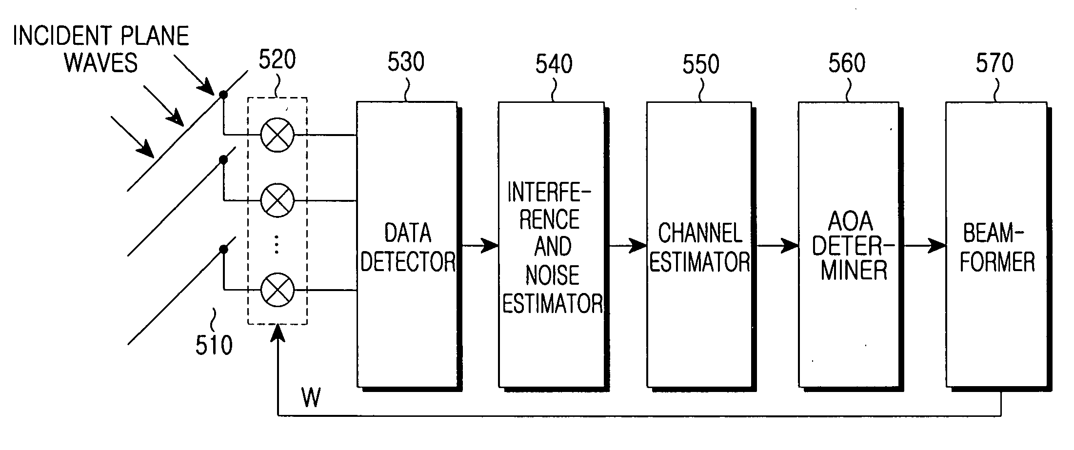
[0046]FIG. 5 is a schematic block diagram illustrating a beam-forming transceiver using a spatial interpolation in accordance with a first exemplary embodiment of the present invention.

[0047] Referring to FIG. 5, a signal received through an array antenna 510, which can comprise incident plane waves received at the antenna elements with different phases, is demodulated to a data signal through a data detector 530. The data signal is input to an interference and noise estimator 540. The interference and noise estimator 540 estimates the interference power and the spectral noise density N0 of the thermal noise power using the data signal provided from the data detector 530. An output of the interference and noise estimator 540 is input to a channel estimator 550. The channel estimator 550 computes channel impulse response information. At this time, channel impulse responses are computed on the basis of antenna elements and users for performing communication through the array antenna ...

second exemplary embodiment

[0097] A second exemplary embodiment as described below determines two angles of arrival closest to the direction in which a user is located, that is, a primary AoA and a secondary AoA, using energy values evaluated at candidate angles of arrival, and computes beam-forming weights (W) at the primary AoA and the secondary AoA.

[0098]FIG. 8 is a schematic block diagram illustrating a beam-forming transceiver using the spatial interpolation and the secondary AoA in accordance with the second exemplary embodiment of the present invention.

[0099] Referring to FIG. 8, a signal received through an array antenna 810, which can comprise incident plane waves received at the antenna elements with different phases, is demodulated to a data signal through a data detector 830. The data signal is input to an interference and noise estimator 840. The interference and noise estimator 840 estimates the interference power and the spectral noise density N0 of the thermal noise power using the provided ...


PUM


Abstract

A beam-forming apparatus and method for improving system performance using a spatial interpolation and at least one Angle of Arrival (AoA) in a system based on regular spatial sampling is provided. The AoA is estimated using a carrier-to-interference ratio. Beam-forming angles are distributed and steered in a predefined scheme such that an identical process is applied in all directions. According to this steering, a linear system model is computed based on regular spatial sampling using regular spatial separation at beam angles. Beam-forming performance is improved by compensating for a difference between adaptive and sector-type arrays. Only the steps of computing a spatial interpolation and determining an angle range for beam-forming using at least one AoA are added. The precision of estimating an AoA and the precision of beam-forming increase without an additional antenna. Because the system is simpler than that of an adaptive beam-forming system, significant gain is obtained.

Description

PRIORITY [0001] This application claims the benefit under 35 U.S.C. § 119(a) of Korean patent application nos. 2005-29630 and 2006-6504, filed Apr. 8, 2005, and Jan. 20, 2006, respectively, in the Korean Intellectual Property Office, the entire contents of both of which are hereby incorporated by reference. BACKGROUND OF THE INVENTION [0002] 1. Field of the Invention [0003] The present invention generally relates to an array antenna system. More particularly, the present invention relates to an apparatus and method for optimal beam-forming for transmitting and receiving high-speed data at high performance based on a regular spatial interpolation. [0004] 2. Description of the Related Art [0005] Reception quality of radio signals is affected by many natural phenomena. One of the natural phenomena is temporal dispersion caused by signals reflected on obstacles in different positions in a propagation path before the signals arrive at a receiver. With the introduction of digital coding i...

Claims


Application Information

Patent Timeline
Patent Type & Authority Applications(United States)
IPC IPC(8): H01Q3/00G01S3/16
CPCG01S3/74H01Q3/26G06F2218/22
Inventor ANN, JONG-HOONKIM, SONG-HUNKIM, BYOUNG-YUNLEE, HYE-YOUNGLEE, HYEON-WOOSEEBENS, ACHIMSCHOLAND, TOBIASJUNG, PETERBURNIC, ADMIRHESSAMIAN-ALINEJAD, ARJANG
Owner SAMSUNG ELECTRONICS CO LTD
Why Eureka
Try Eureka