Thin vapor-chamber structure

Pending Publication Date: 2022-01-06
DELTA ELECTRONICS INC
View PDF8 Cites 0 Cited by
  • Summary
  • Abstract
  • Description
  • Claims
  • Application Information

AI Technical Summary

Benefits of technology

This patent describes a thin vapor-chamber structure that uses a wick with micro-channels to provide the necessary wicking power for fluid to flow from the evaporation zone to the condensation zone. The clustered patterns on two covers are arranged and connected to form a micro-channel, which is in direct contact with the liquid-phase fluid. The wicking power is controlled by adjusting the height, width, and spacing distance of the protruding stripes on the covers. This structure prevents interference between the vapor-phase and liquid-phase fluids, and also prevents droplets scattering that could affect performance. The covers are connected by an adhesive layer, which simplifies the manufacturing process and reduces energy consumption. Overall, this patent provides a thin vapor-chamber structure with effective wicking power and improved performance.

Problems solved by technology

The vapor-phase fluid and the liquid-phase fluid formed by the working fluid flow relatively in the extremely small chamber space, which is likely to interfere with each other and cause droplets scattering in the working fluid.
Consequently, the performance of the vapor chamber is affected.
Consequently, the working efficiency of the vapor chamber is affected.

Method used


Image

  • Thin vapor-chamber structure
  • Thin vapor-chamber structure
  • Thin vapor-chamber structure

Examples


Embodiment Construction

[0034]The present disclosure will now be described more specifically with reference to the following embodiments. It is to be noted that the following descriptions of preferred embodiments of this disclosure are presented herein for purpose of illustration and description only; it is not intended to be exhaustive or to be limited to the precise form disclosed.

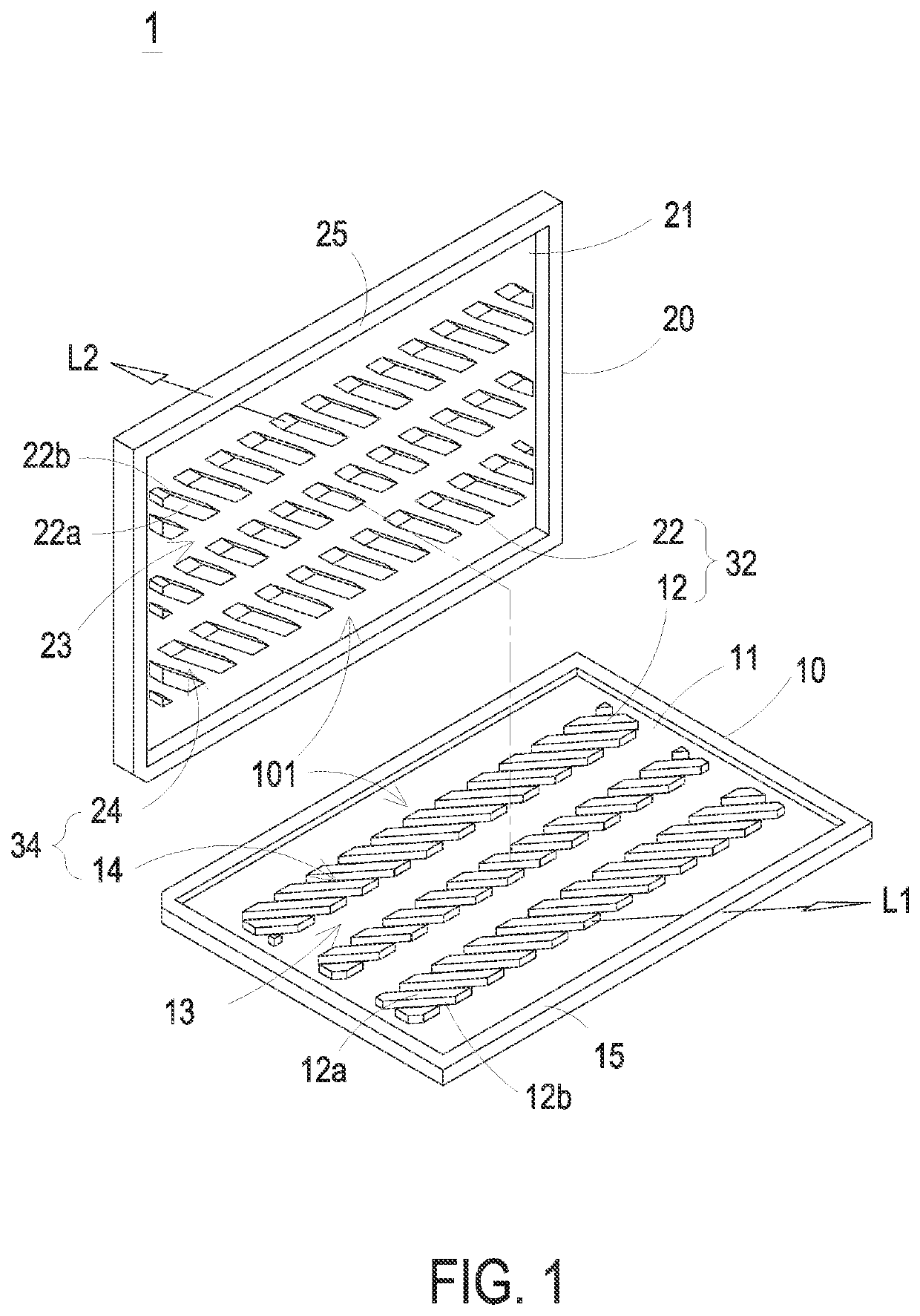
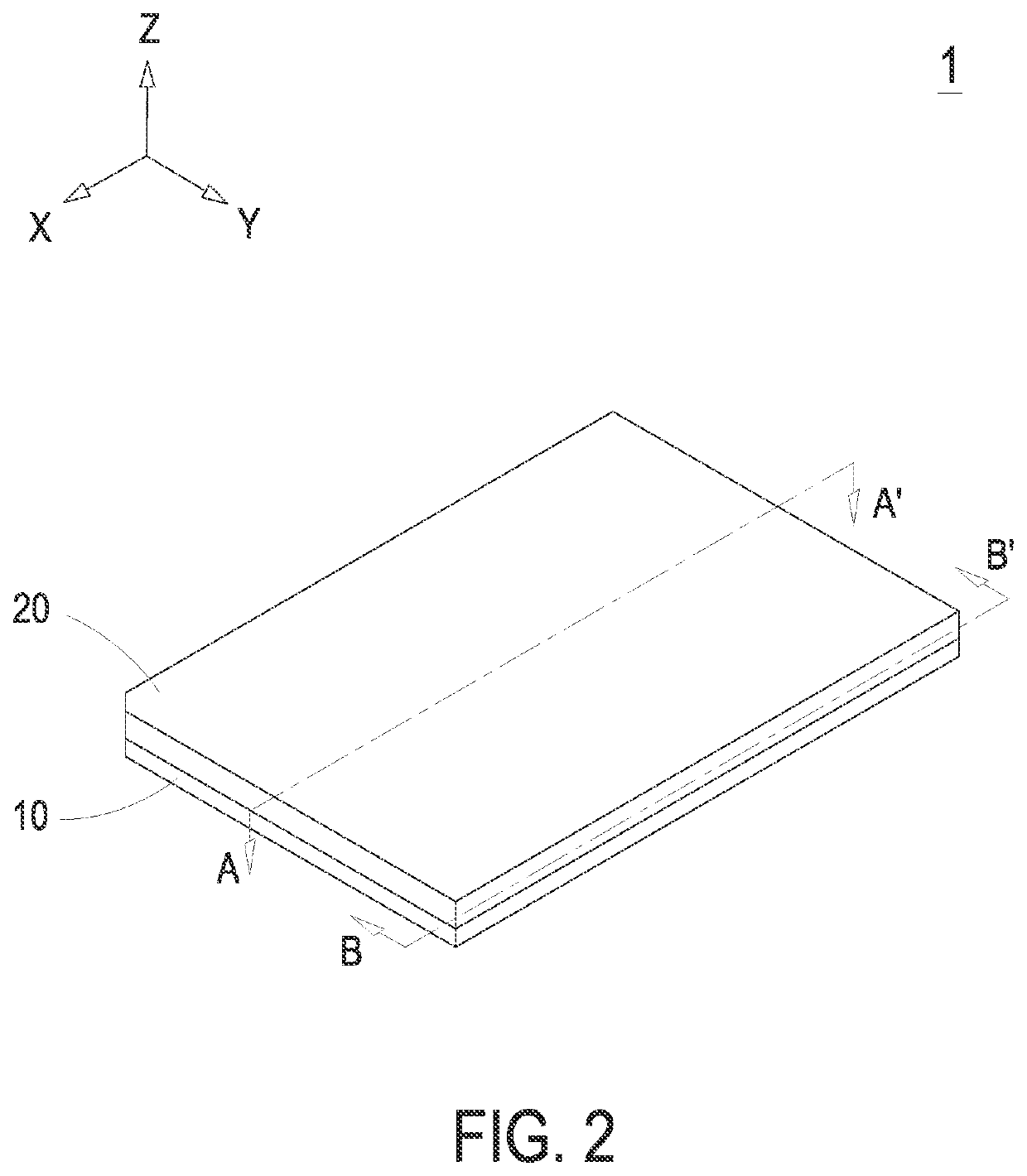
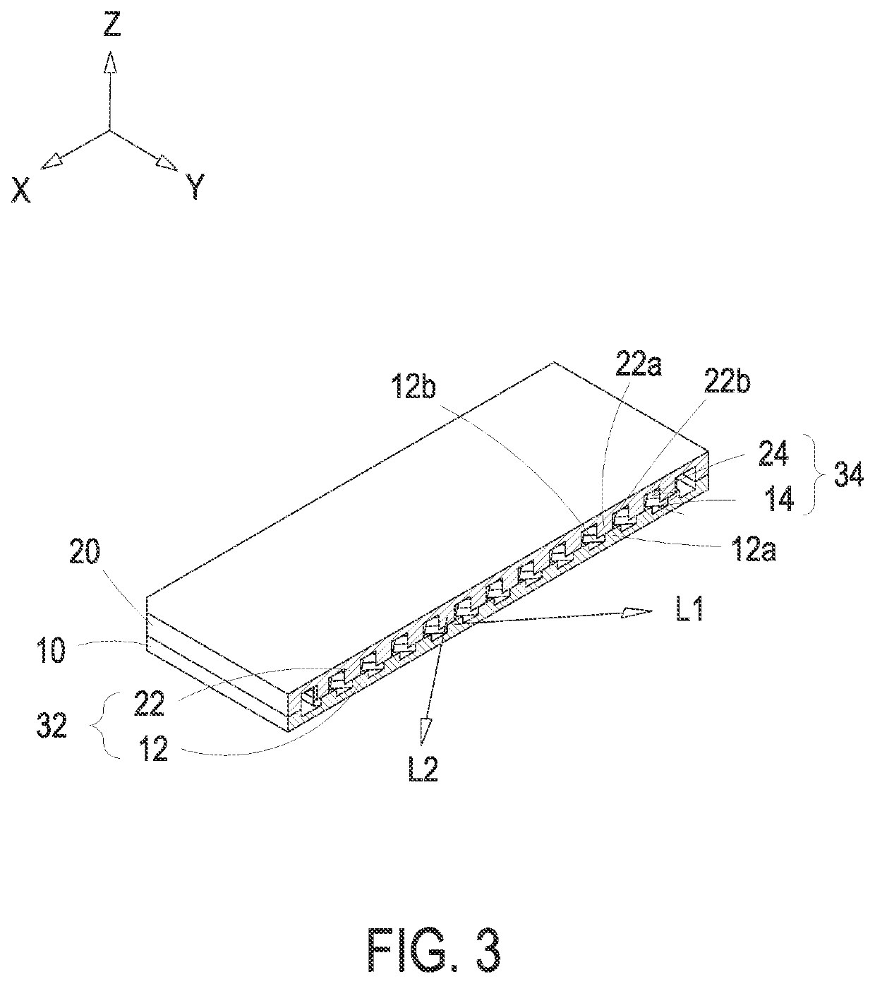
[0035]FIG. 1 shows an exploded view of the thin vapor-chamber structure according to a first embodiment of the present disclosure. FIG. 2 shows a perspective view of the thin vapor-chamber structure according to the first embodiment of the present disclosure. FIG. 3 shows a cross-sectional view of the thin vapor-chamber structure of FIG. 2 taken along the line A-A′. FIG. 4 is a lateral view of FIG. 3. FIG. 5 shows a cross-sectional view of the thin vapor-chamber of FIG. 2 taken along the line B-B′. FIG. 6 is a top view of FIG. 5. In the embodiment, the thin vapor-chamber structure 1 includes a first cover 10, a second cover 20 ...


PUM


Abstract

The disclosure relates to a thin vapor-chamber structure including a first cover and a second cover. The first cover has a first surface and a first clustered pattern. The first clustered pattern is disposed on the first surface, and has a plurality of first protruding stripes spaced apart from each other and extended along a first direction. The second cover has a second surface and a second clustered pattern. The first surface faces the second surface. The second clustered pattern is disposed on the second surface, and has a plurality of second protruding stripes spaced apart from each other and extended along a second direction. The first clustered pattern and the second clustered pattern are partially contacted with each other to form a wick. The lateral walls of the first protruding stripes and the second protruding stripes form a micro-channel meandering between the first surface and the second surface.

Description

FIELD OF THE INVENTION[0001]The present disclosure relates to a vapor-chamber structure, and more particularly to a thin vapor-chamber structure for effectively eliminating the influence of vapor-liquid interference on the wicking power.BACKGROUND OF THE INVENTION[0002]A conventional vapor-chamber structure includes a hermetically sealed hollow vessel, a working fluid, and a closed-loop capillary recirculation system. With the liquid-vapor phase change of the working fluid, the functions of rapid heat transfer and heat diffusion are achieved.[0003]However, the conventional vapor-chamber structure has a micro-structure formed by for example a copper mesh to generate a capillary force, and the working fluid in the conventional vapor-chamber structure is driven to circulate through evaporation and condensation. As the conventional vapor-chamber structure tends to be thinner, the chamber space of the hollow vessel is getting smaller. The vapor-phase fluid and the liquid-phase fluid form...

Claims


Application Information

Patent Timeline
IPC IPC(8): F28D15/04
CPCF28D15/04F28D15/046F28D15/0233F28F2240/00F28F2225/04
Inventor LEE, KUO-YINGCHANG, CHE-WEILU, CHAO-WENSU, CHERNG-YUH
Owner DELTA ELECTRONICS INC
Why Eureka
Try Eureka