
Phototransistor apparatus and method of operating the phototransistor apparatus

a phototransistor and apparatus technology, applied in the field of light sensitive electronic devices, can solve the problems of high current passing through, high energy consumption, and slow switching speed of the phototransistors, and achieve the effects of enabling phototransistor operation, low energy consumption, and increasing the life of the battery

Pending Publication Date: 2022-01-06
HONEYWELL INT INC
View PDF9 Cites 0 Cited by
  • Summary
  • Abstract
  • Description
  • Claims
  • Application Information

AI Technical Summary

Benefits of technology

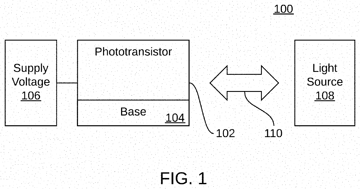
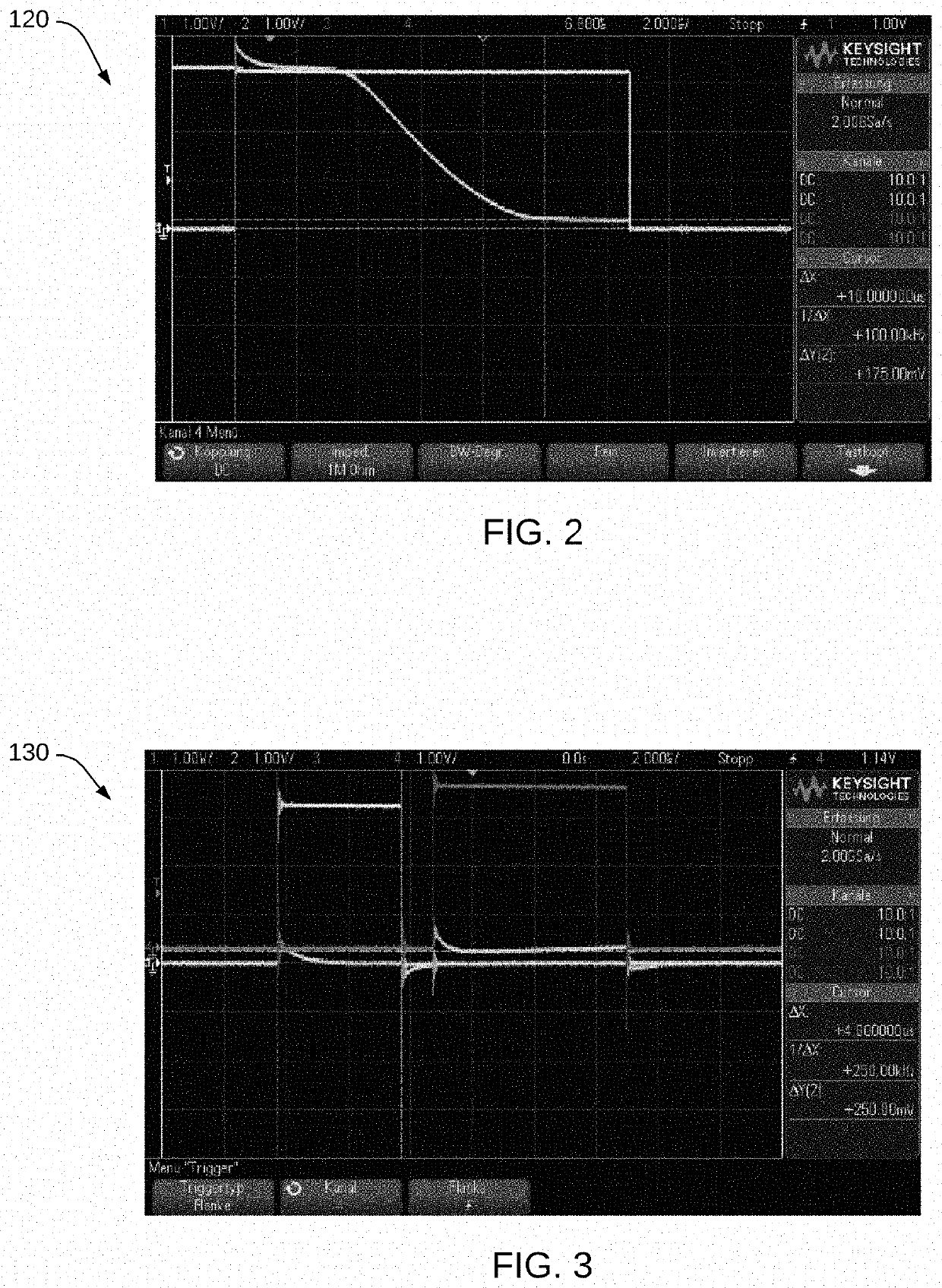
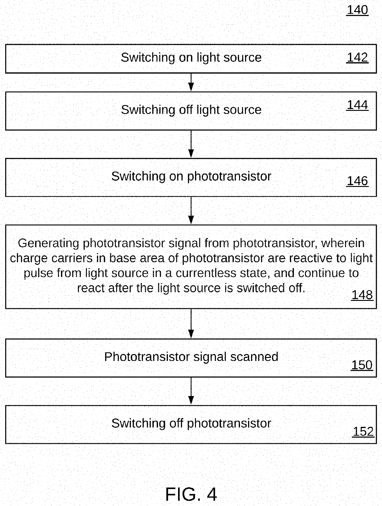
The patent describes a phototransistor apparatus that uses the advantages of the phototransistor light barrier to operate with low energy consumption. The apparatus includes a phototransistor, a light source, and a supply voltage associated with the phototransistor. The supply voltage is switched on after the light source, allowing the phototransistor to generate a signal that can be scanned. The apparatus also includes a delay in switching the power supply of the phototransistor compared to the switching on of the light source, resulting in significant current saving. This results in increased battery life for battery-powered devices, reducing battery costs.

Problems solved by technology

This can cause a relatively high current to pass through the phototransistor.
In battery-powered systems, however, the slow switching speed of the phototransistors often has a negative effect, since this requires a longer duration of the light impulses.
This results in higher energy consumption and thus larger and more expensive batteries must be used.

Method used


Image

  • Phototransistor apparatus and method of operating the phototransistor apparatus
  • Phototransistor apparatus and method of operating the phototransistor apparatus
  • Phototransistor apparatus and method of operating the phototransistor apparatus

Examples


Embodiment Construction

[0023]The particular values and configurations discussed in these non-limiting examples can be varied and are cited merely to illustrate one or more embodiments and are not intended to limit the scope thereof.

[0024]Subject matter will now be described more fully hereinafter with reference to the accompanying drawings, which form a part hereof, and which show, by way of illustration, specific example embodiments. Subject matter may, however, be embodied in a variety of different forms and, therefore, covered or claimed subject matter is intended to be construed as not being limited to any example embodiments set forth herein; example embodiments are provided merely to be illustrative. Likewise, a reasonably broad scope for claimed or covered subject matter is intended. Among other issues, subject matter may be embodied as methods, devices, components, or systems. Accordingly, embodiments may, for example, take the form of hardware, software, firmware, or a combination thereof. The fo...


PUM


Abstract

A phototransistor apparatus and a method of operating the phototransistor apparatus. The phototransistor apparatus can include a phototransistor, a light source, and a supply voltage associated with the phototransistor. After switching on the supply voltage, the phototransistor can generate a phototransistor signal that is scanned, wherein the supply voltage associated with the phototransistor is switched on later than the light source, and wherein charge carriers in a base area of the phototransistor are reactive to a light pulse from the light source in a currentless state, and continue to react after the light source is switched off. Alternatively, the power supply of the phototransistor can be switched on before the light source is switched off. By delaying the switching on of the power supply of the phototransistor compared to the switching on of the light source, a significant current saving can be achieved.

Description

CROSS-REFERENCE TO PROVISIONAL APPLICATION[0001]This patent application claims priority under 35 U.S.C. § 119(e) to U.S. Provisional Patent Application Ser. No. 63 / 047,132 entitled “Phototransistor Apparatus and Method of Operating the Phototransistor Apparatus,” which was filed on Jul. 1, 2020, the disclosure of which is incorporated herein by reference in its entirety.TECHNICAL FIELD[0002]Embodiments relate to light sensitive electronic devices such as phototransistors. Embodiments further relate to phototransistors used in gas meters including diaphragm gas meters.BACKGROUND[0003]A phototransistor is a type of device that can convert light signals into electric signals. Phototransistors are similar to photoresistors in that both can modulate current and voltage. A phototransistor can be configured a bipolar semiconductor and can focus the energy that is passed through it. Photons (light particles) activate phototransistors and are used in virtually all electronic devices that dep...

Claims


Application Information

Patent Timeline
IPC IPC(8): G01J1/44
CPCG01J1/44G01J2001/4473
Inventor GERDES, CLAASSCHRODER GENANNT BERGHEGGER, RALF HEINRICHWALLMEYER, AUGUST
Owner HONEYWELL INT INC
Learn More